


Facilities
| Overview | |
|---|---|
|
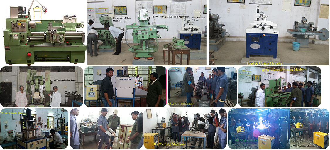
The central workshop, a central facility, was merged with the Department of Mechanical Engineering in the year 1992. The Workshop consists of Fitting Shop, Welding shop, Carpentry shop, Power Tools shop, Foundry Shop, Machine Shop and House wiring shop. The facilities are used for the conduction of regular sessional classes as a part of the curriculum for students at various levels pertaining to different departments. In addition to housing many conventional machines and equipment it also has most modern fabrication and production units in tune with the recent technological developments. Some of these include Electro Chemical Machine, EDM, Tig and Mig welding machines, Tool and cutter Grinding Machine, Mitutoyo Tool Makers Microscope, Kistler 3 component force measurement Dynamometer, Variable Speed Precision Lathe, Tool Monitoring Equipment during machining and CNC Engraving Machine etc. Steps are afoot for further modernization of the central workshop utilizing the funds made available through MHRD / MODROBS / TEQIP etc. Workshop facilities are extended to facilitate execution of different projects / research work at UG, PG and Doctoral level, under the guidance of the respective guides. |
|
Design Engineering Labs
|
To facilitate the smooth running of lab course of UG and PG that require computational resource and also project works of the students and faculty. Lab CoverageModeling, Simulation and Analysis: Solid Modeling, Programming, DIN/ISO programming, CNC training. |
| A — Kinematic Models | B — Dynamics |
|---|---|
|
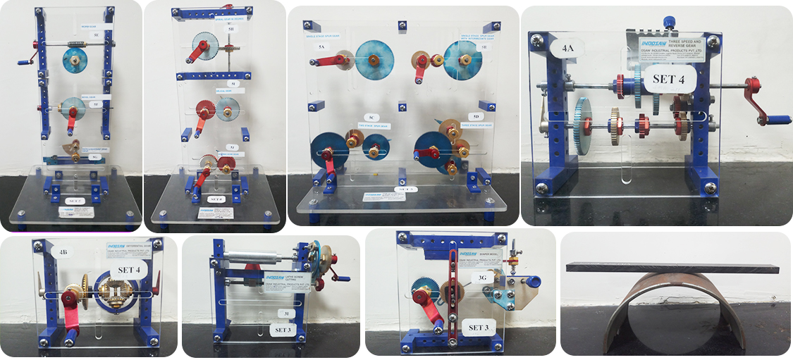
Inversions of four bar and Slider Crank Mechanism: Four bar Mechanism, Elliptical Tracer, Scotch yoke mechanism, Oldham coupling, Crank oscillating drive, slider crank, Crank and slotted link mechanism. Lower pairs: Pantograph Mechanism, Peaucellier drive, Watt's Mechanism, Cycloidal motion. Gears and Gear Trains: Spur gear (single and Multi-Stage), Helical Gear, Bevel gear, Herringbone gear, Worm gear, Rack and pinion arrangement; Compound gear train, Reverted gear train, Epicyclic gear train, sun and planet gear. Cams and Clutches: Geneva Drive, radial, cylindrical and face cams; Centrifugal clutch, Cone clutch and dog clutch. Belt drives: Flat Belt drive, Belt drive, Chain Drive, Friction wheel drive, multi stage and contra rotation belt drives, Frictional wheel drive. |
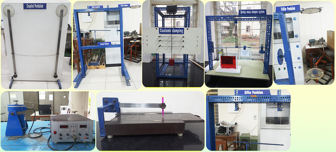
Undamped free vibrations-I: Estimate the acceleration due to gravity using Bifilar Pendulum; Determine the mass moment of inertia of a given object using trifilar pendulum; Compound Pendulum (Cg and MI). Undamped free vibrations-II: Find fn of (i) a bar resting on a cylindrical surface (ii) a semi cylindrical shell resting on a horizontal surface; Locate centre of mass G and the MI about G of a CR. Damped Free Vibrations I: Determine the viscous damping coefficient of a given viscous damper; Estimate the damping in a given vibrating spring through logarithmic decrement. Damped Free Vibrations II: Determine the coefficient of Friction between two surfaces using Coulomb damping equipment. Two degree of Freedom System: Coupled pendulum — natural frequencies through normal mode of vibrations and Beat Phenomenon. Cantilever Beam: Examine mode shapes using Vibration Exciter power oscillator setup. Balancing Apparatus: Demonstration of imbalance vibration at different speeds and perform balancing operation. Universal Vibration System: Experiments with pendulums, bar-type oscillators, damped and undamped resonance, absorber effect in multi-mass oscillators. Whirling of Shafts: Investigation of Laval rotor (critical speed, self-alignment), Natural modes on a shaft with continuous mass distribution (varying bearing clearances, shaft diameters and lengths). |
|
|
| Description | |
|---|---|
|
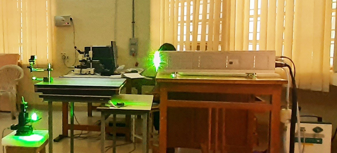
Laser texturing is a process that alters a material's surface properties by modifying its texture and roughness. The laser beam creates micropatterns on the surface through laser ablation, removing layers with micrometer precision and perfect repeatability; typical patterns include dimples, grooves, and free forms. Laser texturing changes surface morphology and surface chemistry of the solid surface thus modifying surface wettability. |
|
| # | Equipment | Specifications & Description |
|---|---|---|
| 1 | Motorised Micro Motion Stage |
Drive details: 0.4 mm pitch lead screw; Positioning accuracy — 0.001 mm; Repeatability — 0.001 mm; Resolution — 0.000125 mm; Speed — 1.6 mm/s.
Stage Range: X-axis: 27157.1875 μm; Y-axis: 29377.5 μm; Z-axis: 26743.4375 μm. The motorized micromotion stage is used for linear movement along three directions (x, y, z-axis) of the specimen placed on the micromotion stage. |
| 2 | Laser Power / Energy Meter |
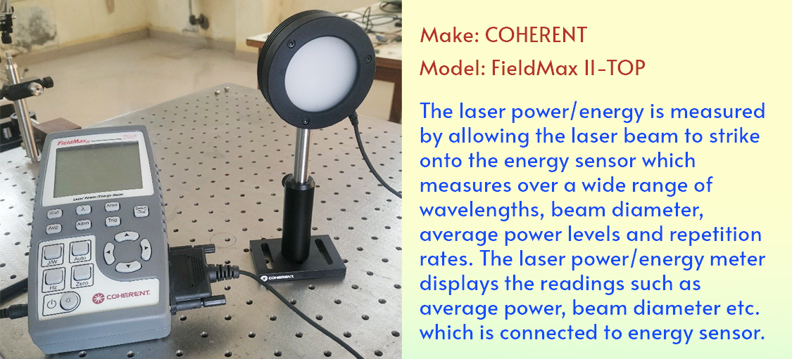
The laser power/energy is measured by allowing the laser beam to strike onto the energy sensor which measures over a wide range of wavelengths, beam diameter, average power levels and repetition rates. The laser power/energy meter displays the readings such as average power, beam diameter etc. which is connected to energy sensor.
|
| 3 | Precision Polarizer Rotator with Linear Movement |
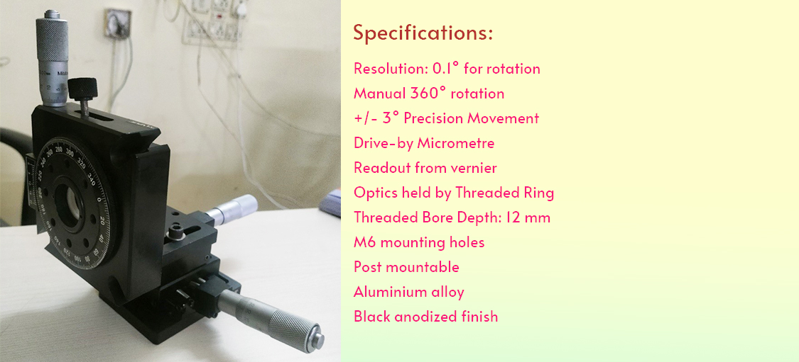
Precision rotary adjustments are possible with this mount. Plate/sheet polarizers are held between two threaded rings inside a threaded bore. The kinematic design of this mount provides fine linear adjustments in two planes for the mounted polarizer.
|
| 4 | Bi-Convex Lens |
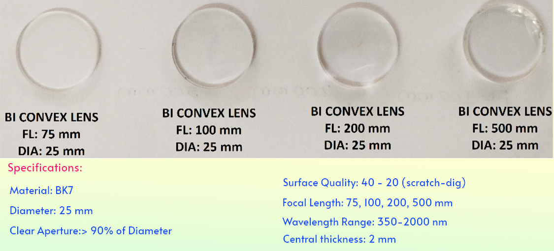
Bi-Convex Lenses are positive spherical lenses having convex surfaces on both sides. These lenses find applications in collecting, focusing, and collimating light. The laser beam size of 8 mm is converged up to 150–200 μm dimple surface texture onto the specimen using a 75 mm focal length lens; a 100 mm FL lens gives a dimple of 200–300 μm, a 200 mm FL lens 300–400 μm, and a 500 mm FL lens textures a dimple of 500–600 μm.
|
| 5 | Breadboard |
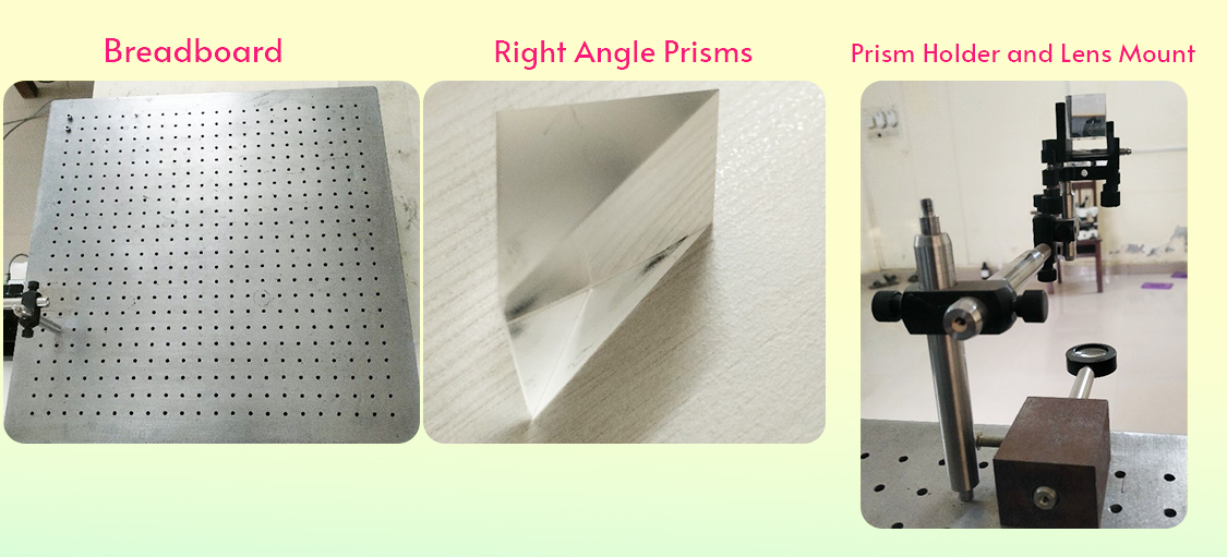
Breadboards are used mainly to construct small optical setups. The thickness of the breadboard is 60 mm. There are tapped holes of 5 mm.
|
| 6 | Right Angle Prisms | Right Angle Prisms are used to redirect a beam of light at 90 degrees from the incident direction or used as a 180° beam retroreflector. |
| 7 | Prism Holder and Lens Mount | Prism holder is used for holding the prism which will direct the laser beam on the specimen by deflecting 90°. Bi-convex lens is mounted on the Lens mount. |
|
This laboratory is mainly to give a practical exposure to the students who are indeed first step of planning theory of vibrations. Most of the experimental setups are fabricated by the students themselves. The student is made to physically experience basic concepts such as normal mode vibrations, natural frequency, mode shapes, beat phenomenon, different types of damping. There is equipment such as Electrodynamic exciter, Portable vibration analyzer which enables the student to do some advanced experiments. Apart from the experiments on vibrations, the lab is also equipped with rotor balancing machine, twin cylinder locomotive balancing machine, gyroscope demonstration, portable balancing machine. It is planned to procure sophisticated experimental setups in the coming years. |
| # | Equipment | Description & Capabilities |
|---|---|---|
| 1 | Tubular Furnace |
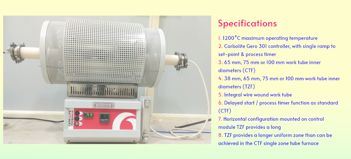
The CTF single zone and TZF 3-zone wire wound tube furnaces use a wire element wound directly onto a fixed diameter integral ceramic work tube. The heated length is divided into 3 zones. An extended uniform zone in the mid-section is achieved with end zone controllers which track the centre zone and compensate for heat loss from the tube furnace ends. Maximum operating temperature: 1200 °C.
Capabilities:
|
| 2 | Planetary Ball Mill |
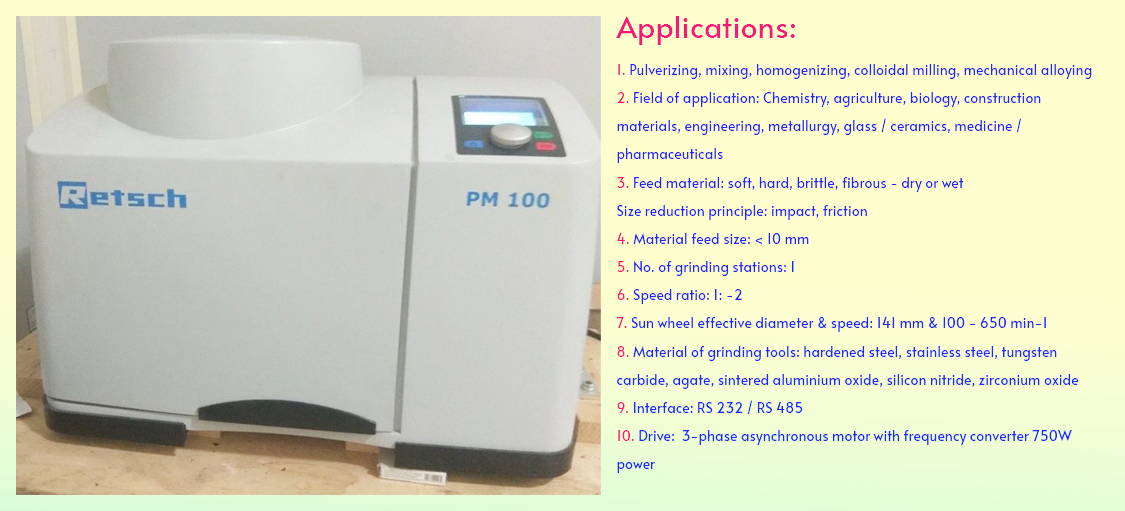
Planetary Ball Mills are used wherever the highest degree of fineness is required. In addition to well-proven mixing and size reduction processes, these mills also meet all technical requirements for colloidal grinding and provide the energy input necessary for mechanical alloying. The extremely high centrifugal forces result in very high pulverization energy and short grinding times. The PM 100 is a convenient benchtop model with 1 grinding station.
Capabilities:
|
| # | Equipment | Description & Capabilities |
|---|---|---|
| 1 | Air Jet Erosion Test Rig |
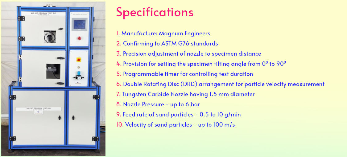
This rig consists of an air compressor, a particle feeder, an air-particle mixing and accelerating chamber. Dry compressed air is mixed with silica sand abrasive particles, which are fed at a constant rate from a conveyor belt into the mixing chamber and then accelerated by passing the mixture through a converging nozzle. These accelerated particles impact the specimen at various angles. Required pressure can be adjusted with the pressure regulator fitted with the machine.
Capabilities:
|
Production Engineering Labs
| Overview | |
|---|---|
|
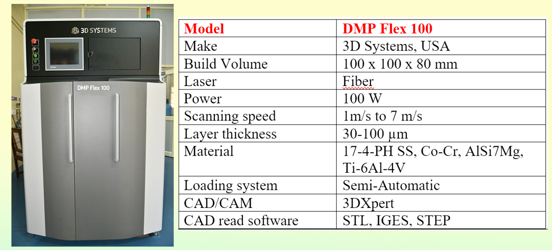
Objective: The Additive Manufacturing Laboratory at NIT Warangal provides students with an active learning environment for fabricating three-dimensional (3D) models directly from CAD data. Students use the laboratory to model and fabricate metal/polymer complex shaped objects used in engineering and medical applications. Lab Coverage
|
|
| # | Equipment / Software | Description & Utility |
|---|---|---|
| 1 | 3DXpert Software |
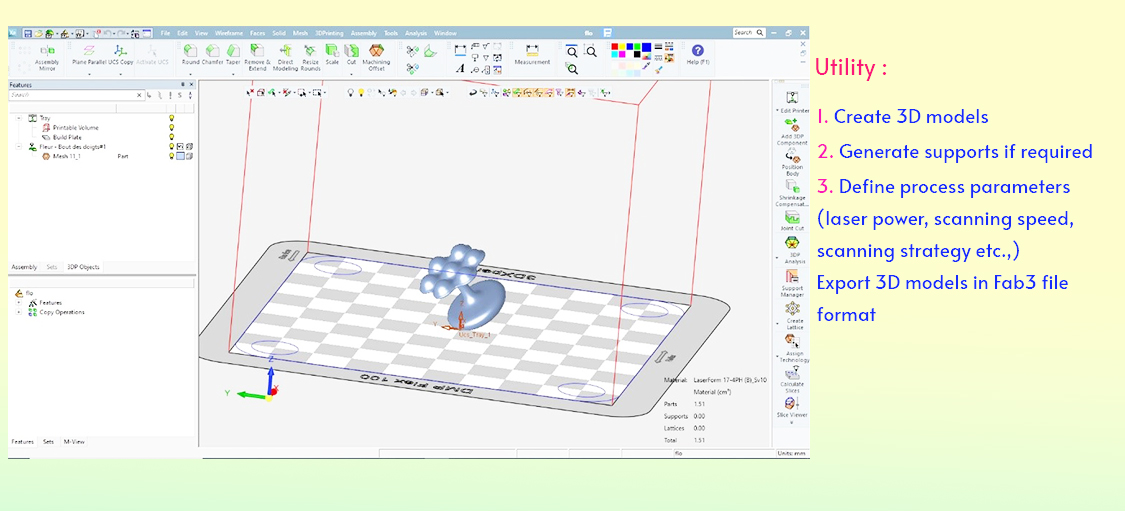
3DXpert is the most advanced and complete software solution for Metal Additive Manufacturing. It offers part preparation, positioning, supports, analysis, printability checks and tray management. Printable lightweight and surface texture lattice structures, Integrated Build Simulation. Capability allows the user to set different scanning strategies for different volumes of the part.
|
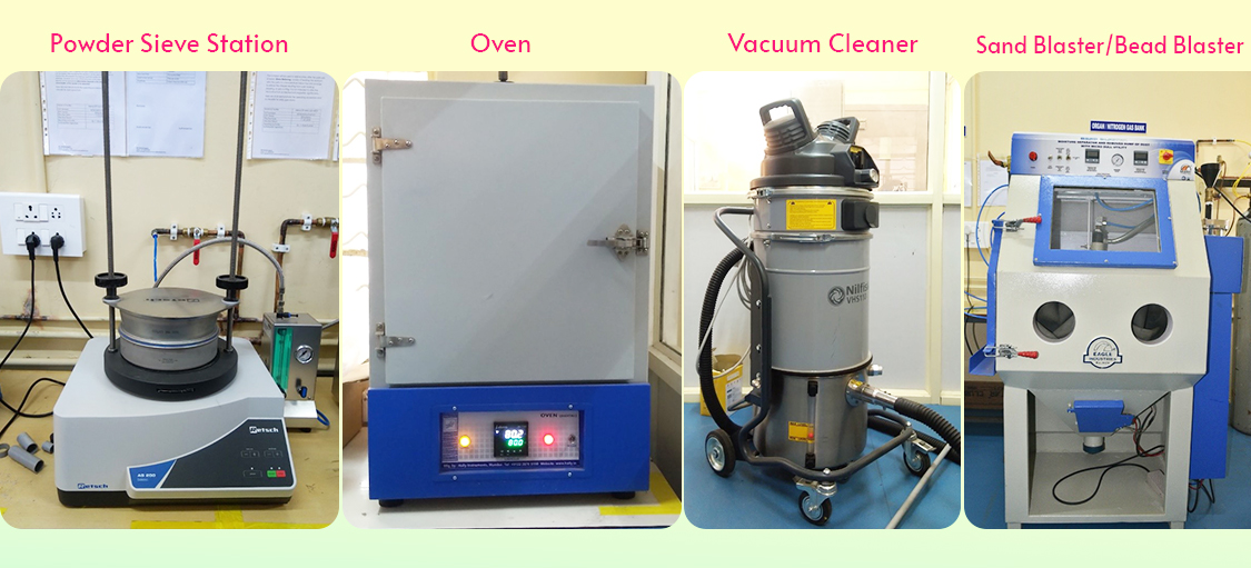
| 2 | Powder Sieve Station | The vibratory sieve shakers of series AS 200 are used in research & development, quality control of raw materials, interim and finished products as well as in production monitoring. The sieve shaker is used to agitate the used material and collect those that can be re-used. The sample is exposed to all the openings in a shield in a manner that will expedite the passing of particles smaller than the openings. |
| 3 | Oven | Consists of three platforms to pre- and post-heat-treat powder to remove moisture absorption inside the powder. |
| 4 | Vacuum Cleaner | The modular design makes it extremely easy to service and upgrade in the field. The simple design makes it easy to clean and sanitize. It needs less maintenance and is suitable for continuous use. It is generally employed in AM lab to remove un-sintered powder from the built part. |
| 5 | Sand Blaster / Bead Blaster |
Operation of forcibly propelling a stream of abrasive material against a surface under high pressure to smooth a rough surface and shape a surface by removing contaminants. A pressurized fluid (typically compressed air) or a centrifugal wheel is used to propel the blasting material.
|
| 6 | Band Saw |
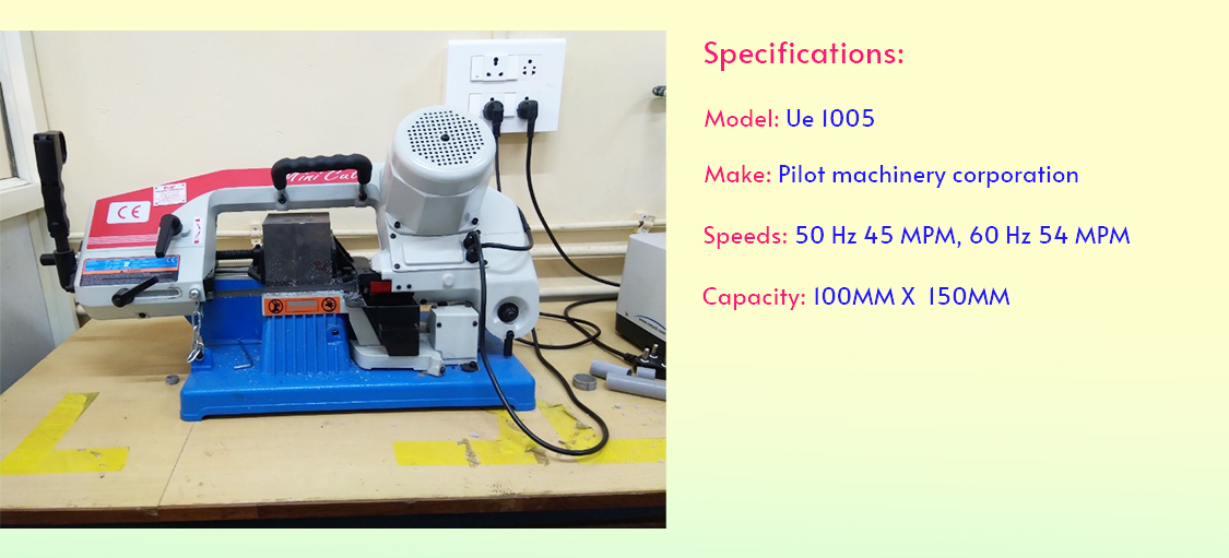
A band saw is a power saw with a long sharp blade consisting of a continuous bond of toothed metal stretched between two or more wheels to cut material. They are used in wood working, metal working and plumbing, but may cut a variety of materials. Here, the band saw is used to cut parts from the plate using a 0.9 mm blade.
|
| 7 | FDM Machine |
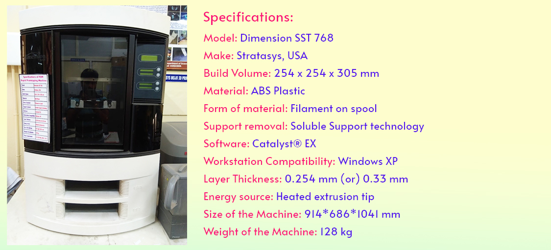
Fused Deposition Modeling (FDM) is a free-form fabrication technology developed by Stratasys®, USA. A plastic filament is unwound from a coil and supplies material to an extrusion nozzle. The nozzle is heated to melt the plastic and has a mechanism which allows the flow of the melted plastic to be turned on and off. The nozzle is mounted to a mechanical stage which can be moved in both horizontal and vertical directions.
Utility:
|
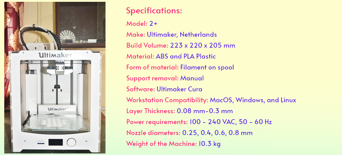
| 8 | Ultimaker 3D Printer |
The filament on spool passes through the nozzle where fusing takes place and is consequently deposited over the build plate as per 3D dimensional data. The process repeats for each cross-sectional layer until producing the final part.
Utility:
|
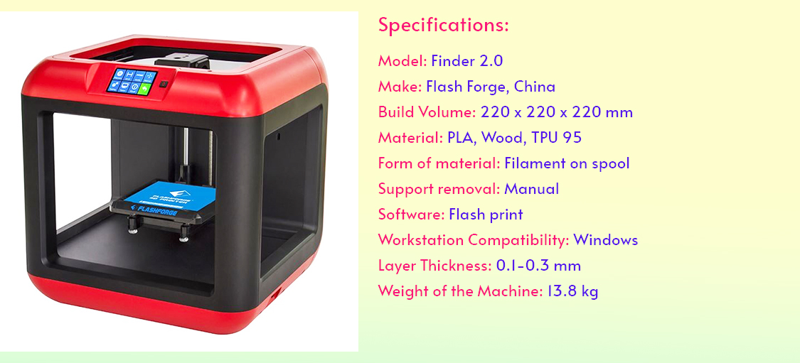
| 9 | Flash Forge 3D Printer |
The filament on spool passes through the nozzle where fusing takes place and is deposited over the build plate as per 3D dimensional data. The process repeats for each cross-sectional layer by XY movement of nozzle and Z movement of substrate to produce the final part.
Utility:
|
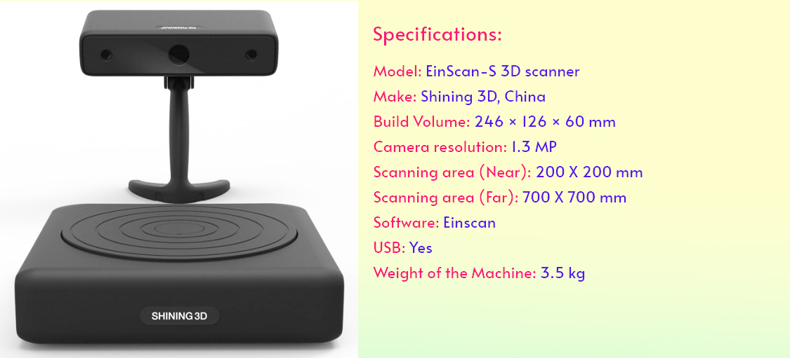
| 10 | 3D Ein Scanner |
The Shining 3D EinScan-S 3D scanner uses structured white light technology. A white light is cast by a projector on the object at the centre of the rotating plate. Degree after degree the plate turns so the object can be 3D scanned from all sides. The process takes around 5 minutes and also captures the textures (colors) of objects.
Utility:
|
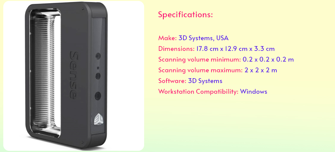
| 11 | Sense 3D Scanner |
The Sense 3D scanner itself is light — hold it in your hand and move around the object to scan it. The scanner projects a patterned infrared (IR) beam onto the object from the bottom opening that is then detected by the middle webcam. On the PC (Windows only), the included software translates the information into the shape of the object. At the top of the Sense is a normal webcam, which the same software uses to translate the captured images into the surface colors of the object.
Utility:
|
| 12 | MIMICS 14.1 Software |
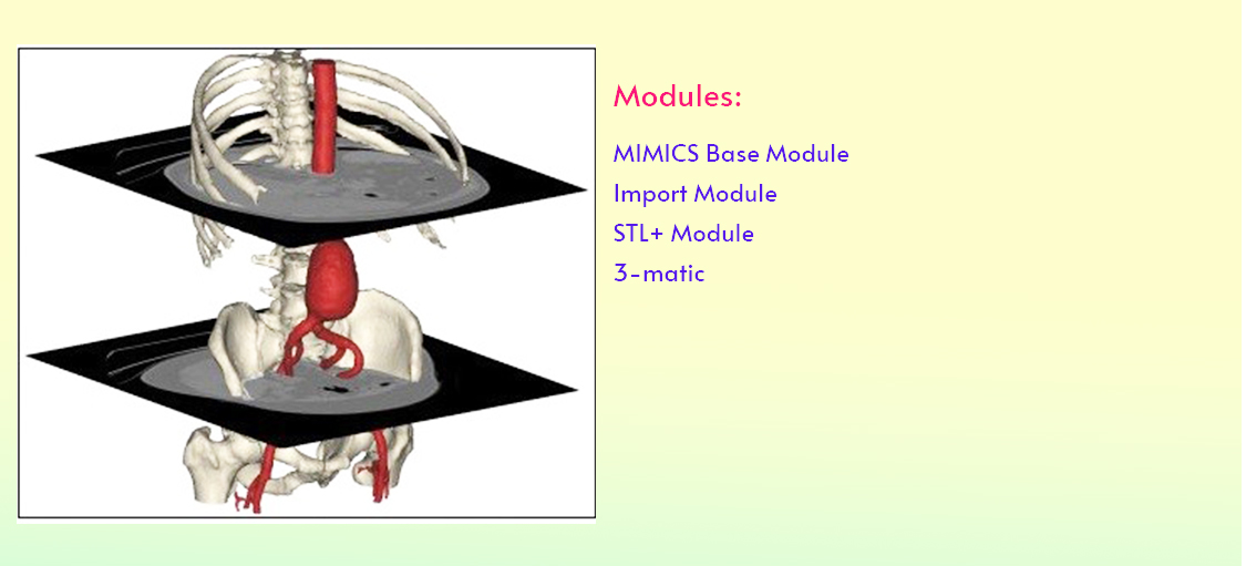
Mimics is software developed by Materialise, Belgium for medical image processing. Use Mimics for the segmentation of 3D medical images (coming from CT, MRI, micro CT, CBCT, Ultrasound, Confocal Microscopy) and the result will be highly accurate 3D models of patient's anatomy. Use these patient-specific models for a variety of applications directly in Mimics, or export the 3D models and anatomical landmark points to 3rd party software, like statistical, CAD, or FEA packages.
Utility:
|
| 13 | Prusa Kit |
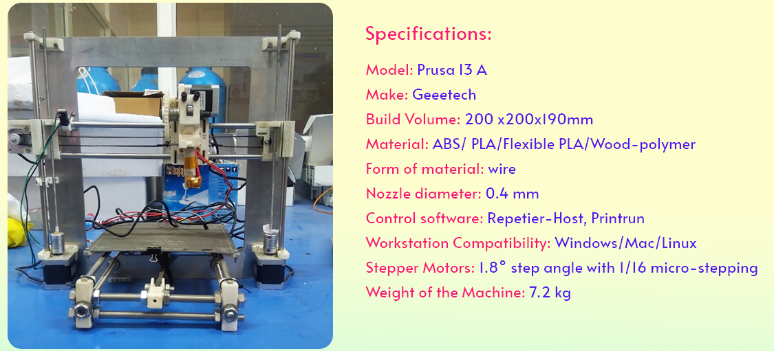
The filament (diameter 1.75 mm) on spool passes through the nozzle where fusing takes place and is deposited over the build plate as per 3D dimensional data. The process repeats for each cross-sectional layer by XY movement of nozzle and Z movement of substrate to produce the final part.
Utility:
|
| # | Equipment | Description & Specifications |
|---|---|---|
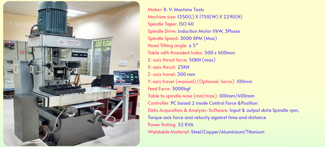
| 1 | Friction Stir Welding Machine |
|
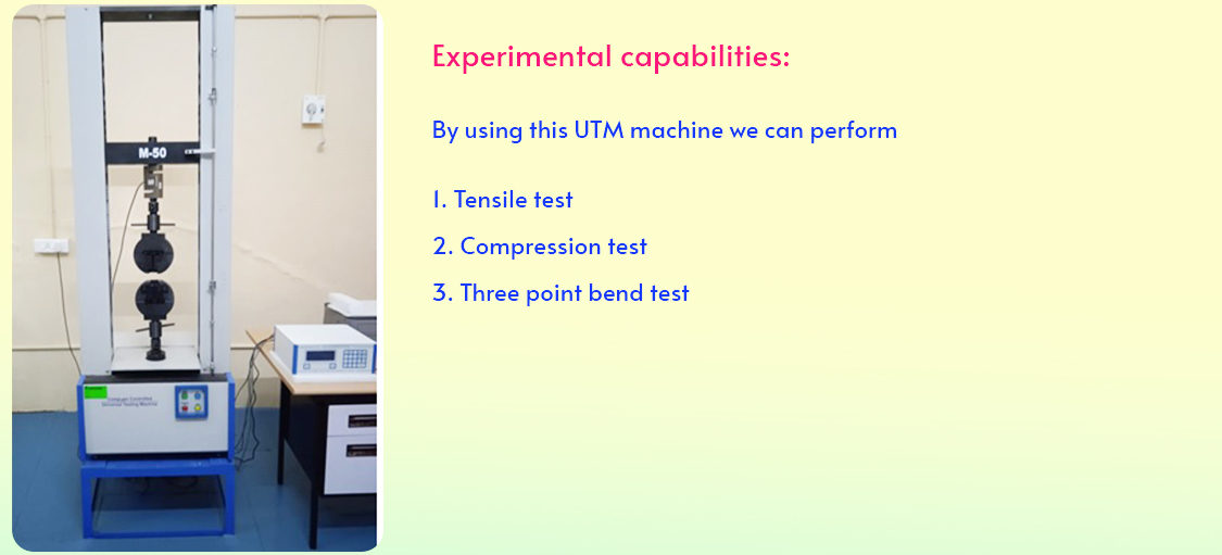
| 2 | Computer Controlled Universal Testing Machine 50 kN capacity |
|
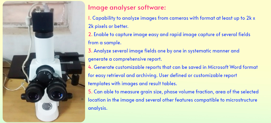
| 3 | Inverted Microscope with Image Analyser Software |
The stage of an inverted microscope is usually fixed, and focus is adjusted by moving the objective lens along a vertical axis to bring it closer to or further from the specimen. The focus mechanism typically has a dual concentric knob for coarse and fine adjustment. The microscope has four objective lenses of different magnifications fitted to a rotating turret known as a nosepiece. Inverted microscopes are used in micromanipulation applications where space above the specimen is required for manipulator mechanisms and microtools, and in metallurgical applications where polished samples can be placed on top of the stage and viewed from underneath using reflecting objectives.
|
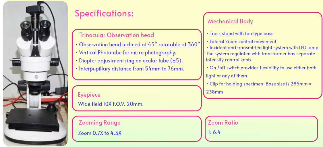
| 4 | Stereozoom Microscope |
|
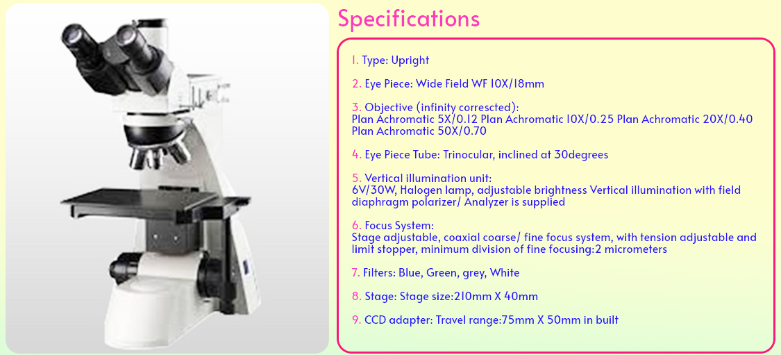
| 5 | Upright Microscope |
|
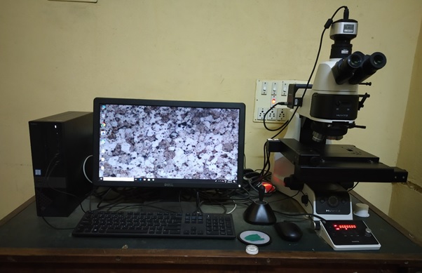
| 6 | 3D Microscope |
 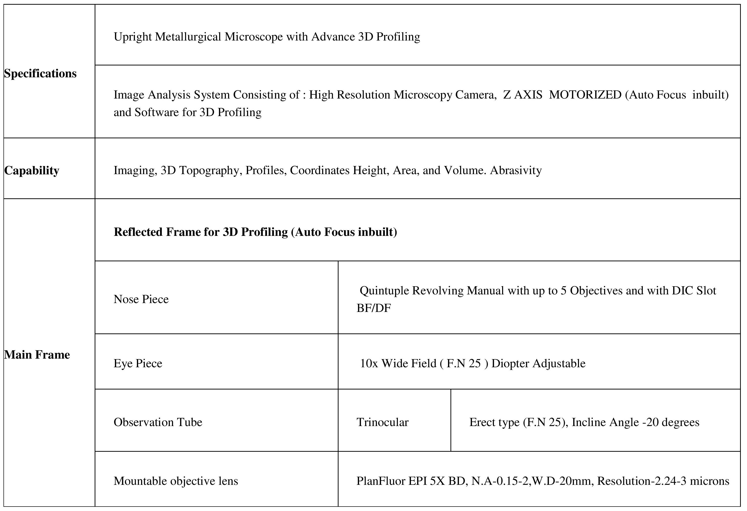 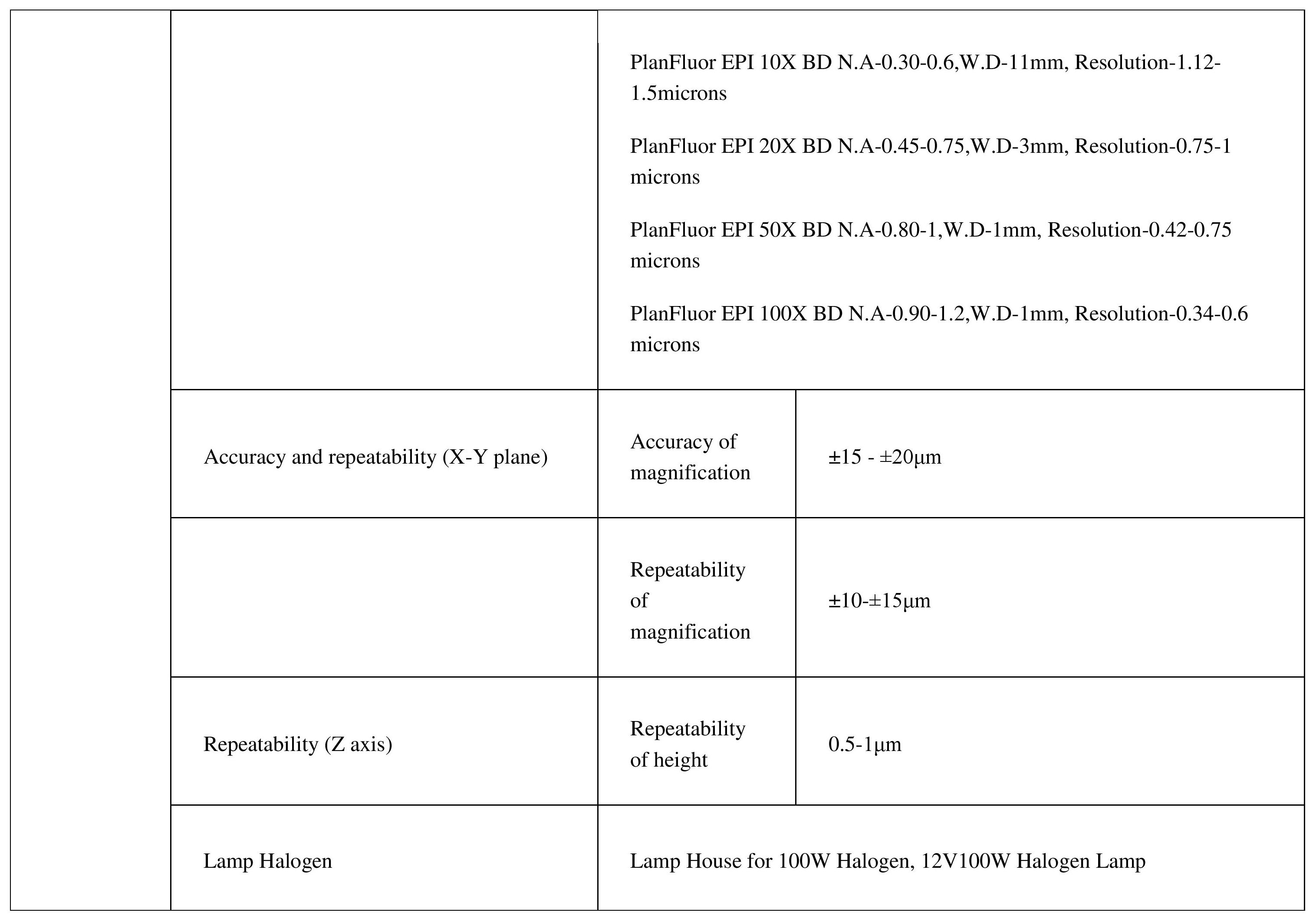 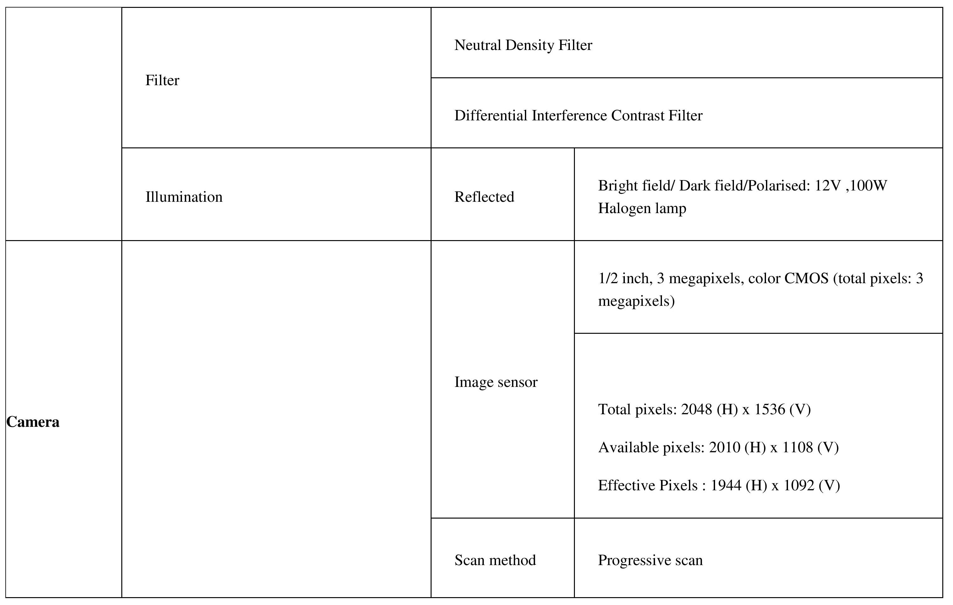 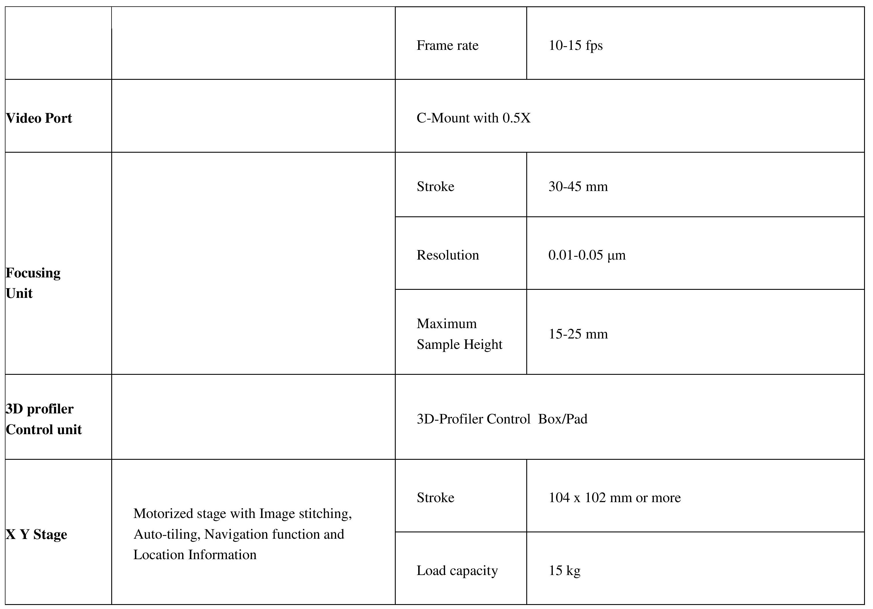 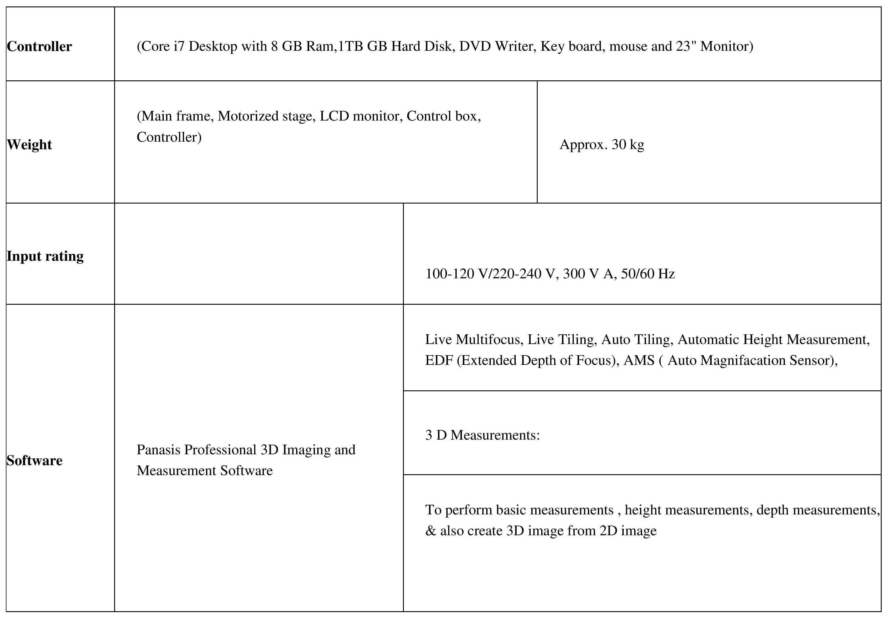 |
| 7 | Rockwell Hardness Tester |
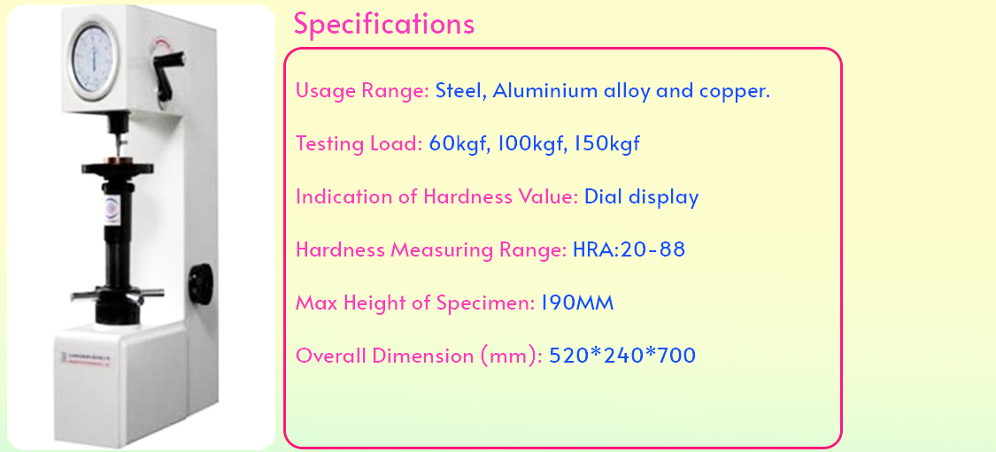
|
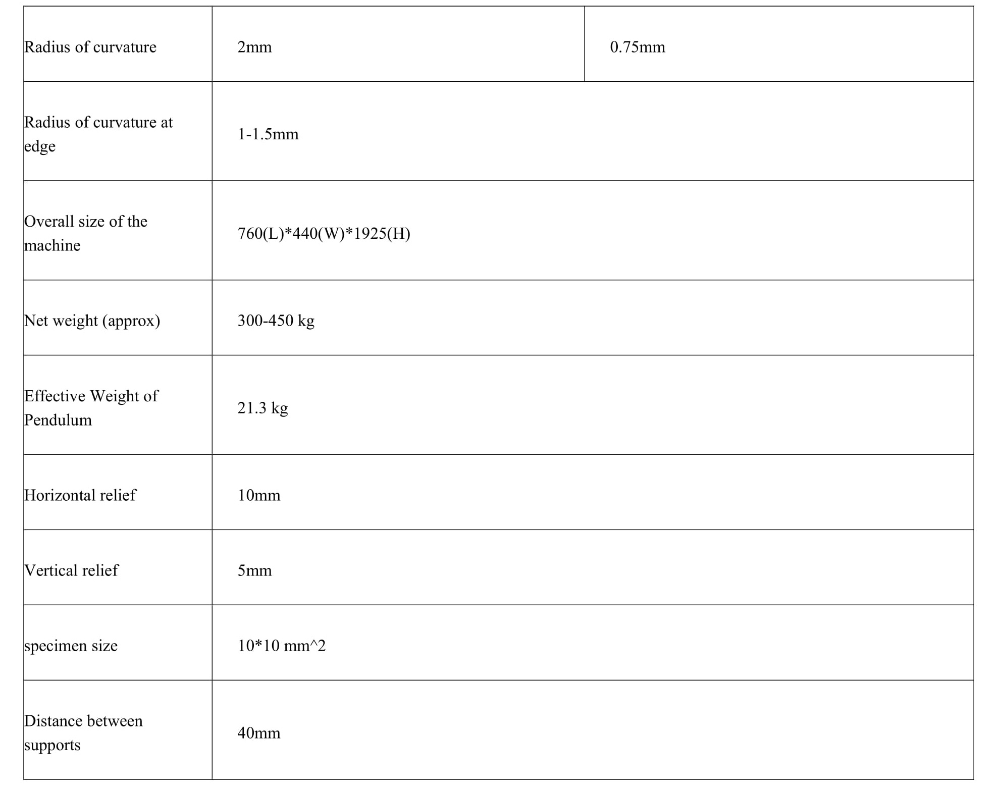
| 8 | Digital Impact Testing Machine |
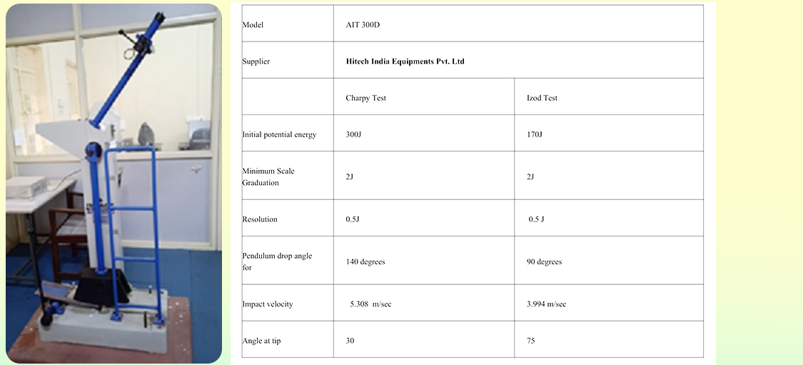 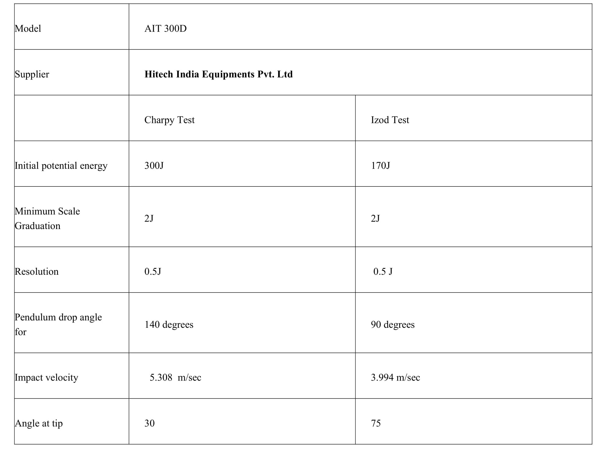  |
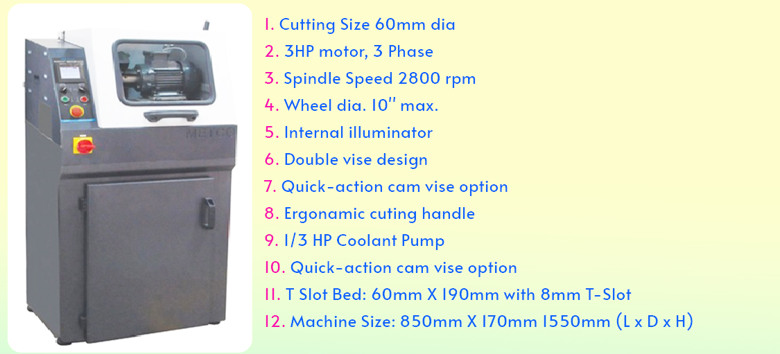
| 9 | Medium Duty Table Top Abrasive Cutter Model: BAINCUT-M |
Light alloy casting base with recirculation coolant system. FRP hood, viewing window, cleaning hose, safety lock included.
|
|
With the emergence of integrated circuits and computers, the frontiers of various traditional disciplines started vanishing. Today, most of the products in the market are neither purely mechanical nor electronic in nature, but are clever integration of components or systems from different engineering disciplines (multidisciplinary). Therefore, there is a pressing need to train engineers/technicians with multidisciplinary skills. |
|
Utility: The Precision Metrology laboratory at NIT Warangal provides students with an active learning environment for the measurement technologies used in production engineering field. Students use the laboratory to collect and analyze measurement data, evaluate measurement methodologies, and learn the capabilities and limitations of measurement technologies. Lab CoverageLinear Measurements, Angular Measurements, Level Measurements, Surface Roughness, Form Measurements, Gear Measurements, Thread Measurements. |
| # | Equipment | Description |
|---|---|---|
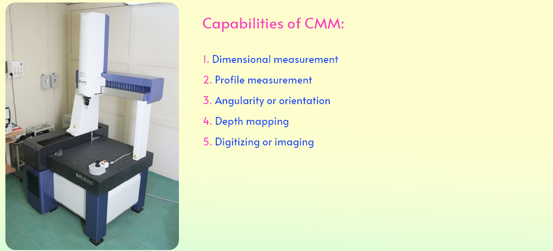
| 1 | Coordinate Measuring Machine (CMM) |
Co-ordinate Measuring Machines (CMM) are mechanical systems consisting of a contact probe and a means of positioning the probe in three-dimensional space relative to the surface of a work part in order to obtain data concerning the part geometry.
|
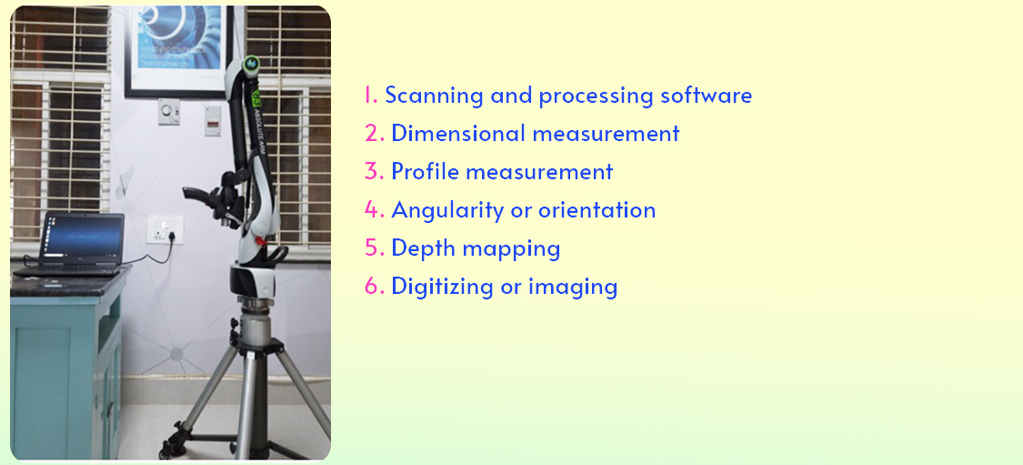
| 2 | Portable CMM (ABSOLUTE ARM) |
A specialized touch measurement tool that also boasts the option for entry-level 3D scanning — the Absolute Arm 6-Axis is one of a kind. Based on technology with Absolute Encoders located at every articulation point and designed with ease-of-movement and usage as a focus, this is a portable measuring arm like no other.
|
| 3 | Profile Projector |
Profile projector is widely used for complex shape stampings, gears, cams, threads and comparing the measured contour model. It's easy to use and high efficient. It is a commonly used measurement of optical instruments.
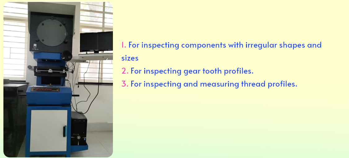
|
| 4 | Ball Milling Machine |
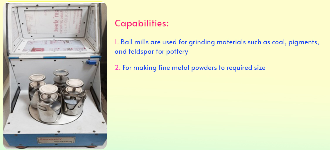
A ball mill, a type of grinder, is a cylindrical device used in grinding (or mixing) materials like ores, chemicals, ceramic raw materials and paints. Ball mills rotate around a horizontal axis, partially filled with the material to be ground plus the grinding medium. Different materials are used as media, including ceramic balls, flint pebbles, and stainless steel balls. An internal cascading effect reduces the material to a fine powder.
|
| 5 | Surface Roughness Tester |
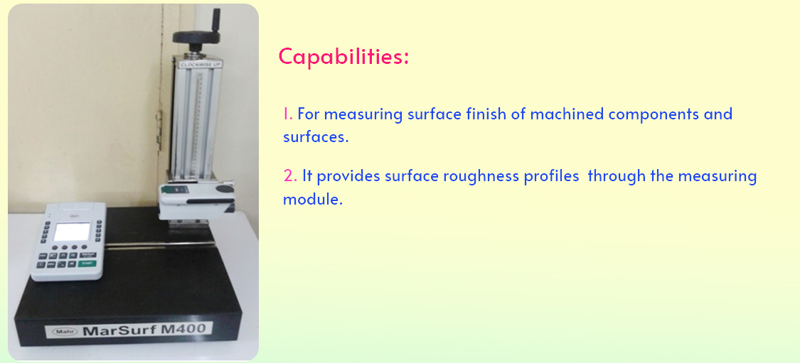
Marsurf surface roughness tester is used in measuring surface roughness of work pieces, machined surfaces through a stylus method.
|
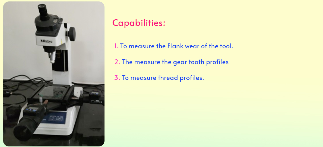
| 6 | Tool Makers Microscope |
|
Lab CoverageSingle point cutting tool preparation with various systems, chip reduction coefficient, helical gear cutting, cutting force measurement, Temperature measurement. |
| # | Equipment | |
|---|---|---|
| 1 | All Geared Lathe Machine | 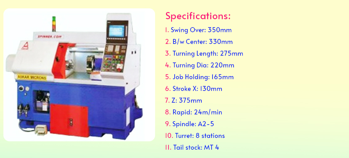 |
| 2 | Pin-on-Disc Machine | 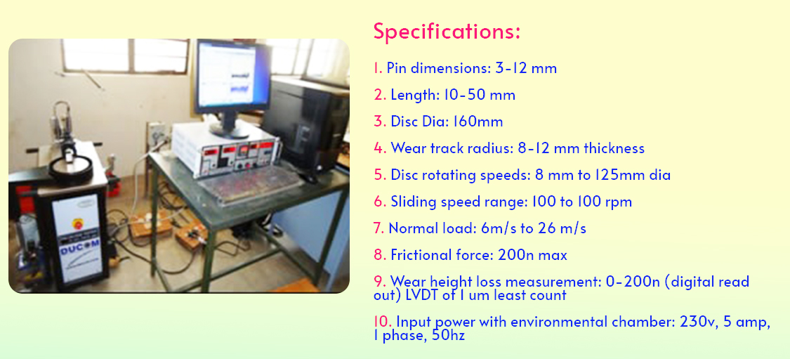 |
| 3 | Bench Drilling Machine | 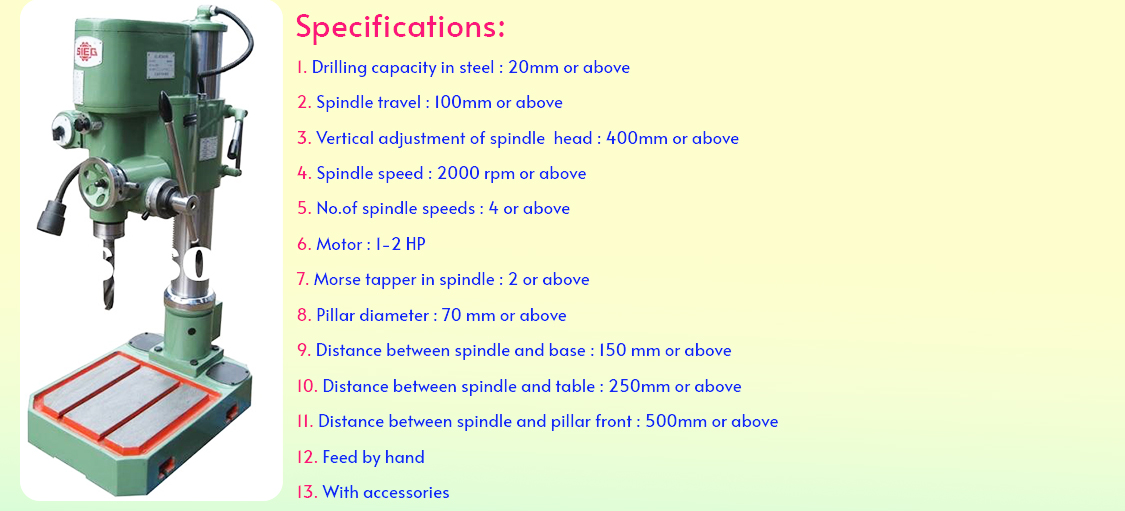 |
| 4 | Hydraulic Feed Unit for Depth Control | Image not available |
| 5 | Hydraulic Power Hacksaw | 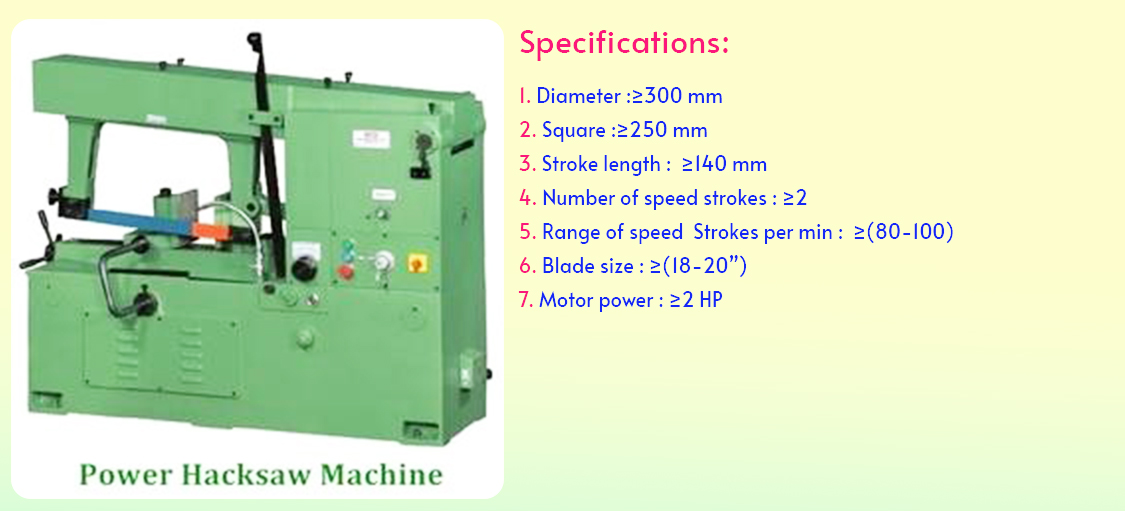 |
| 6 | CNC Retrofitting VDF Lathe | 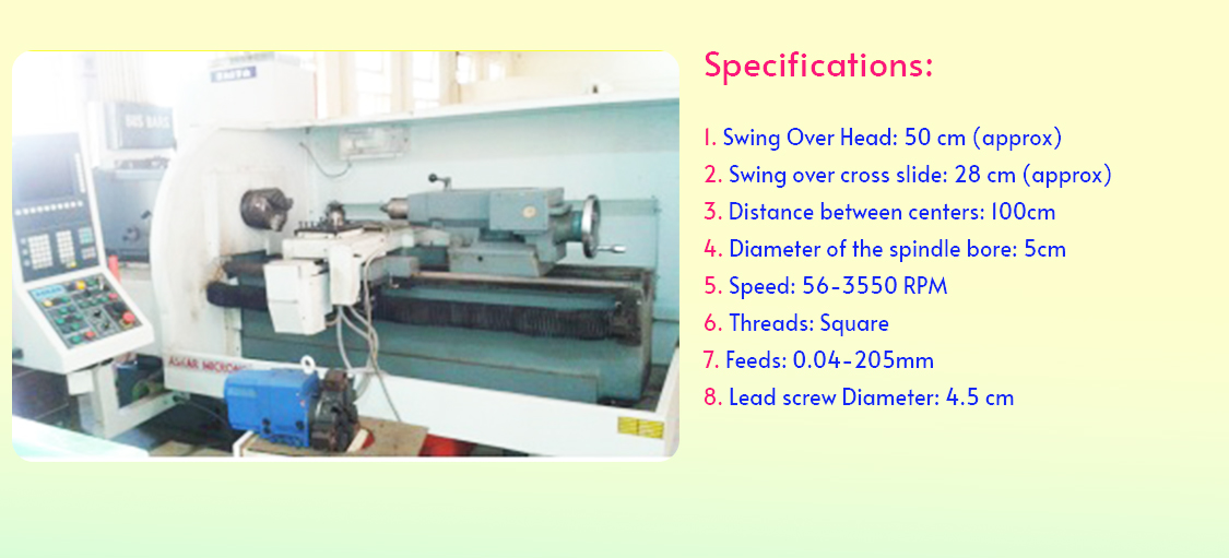 |
| 7 | CNC Milling Machine (M TAB) | 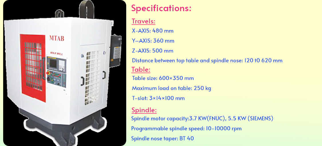 |
| 8 | ASRS System | 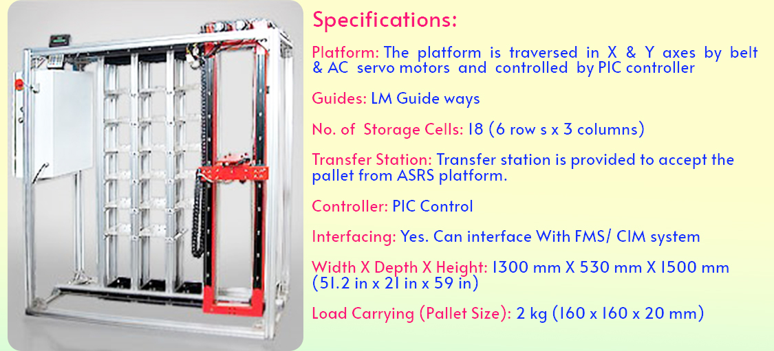 |
| 9 | Six Component Dynamometer | 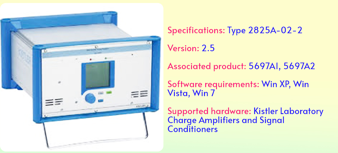 |
| 10 | Planetary Micro Mill Premium Line (Pulverisette 7) | 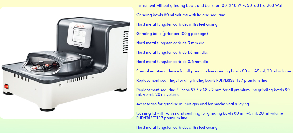 |
| 11 | CNC Control Training System |
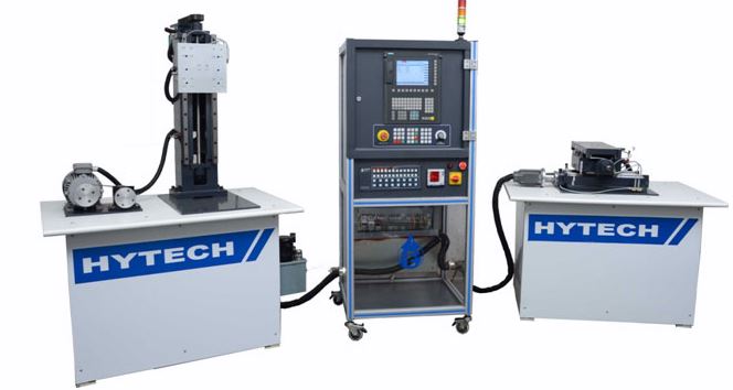 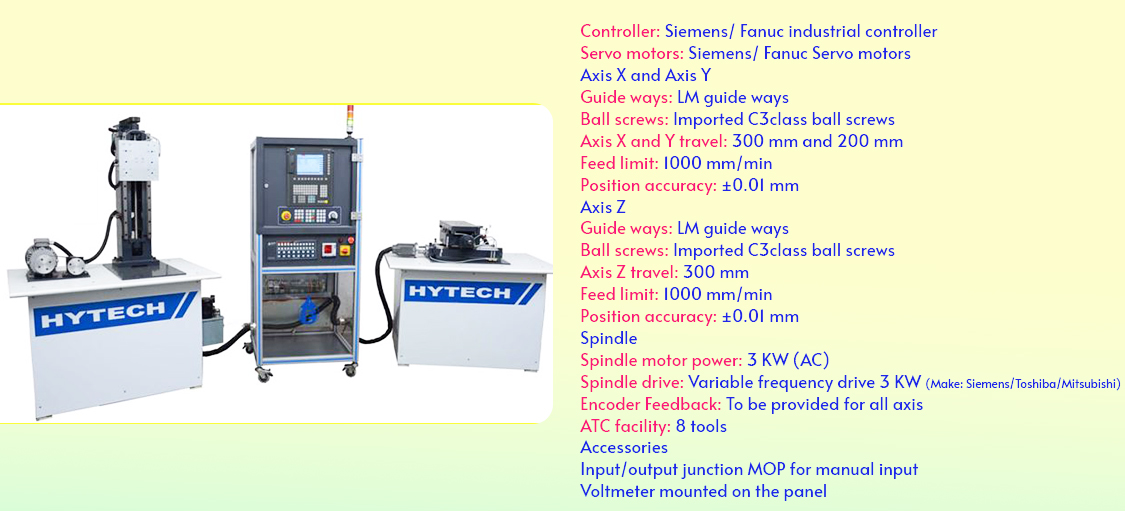 |
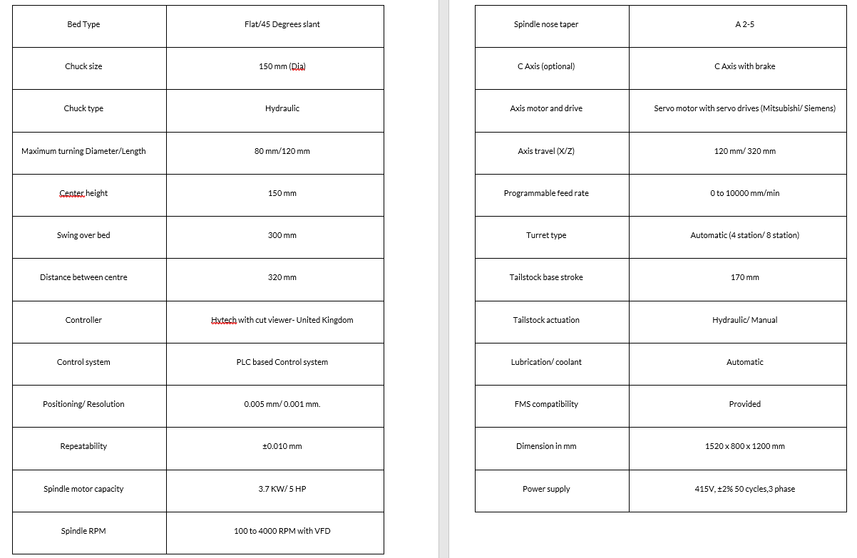
| 12 | CNC Lathe Trainer |
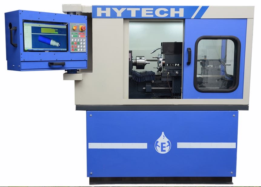  |
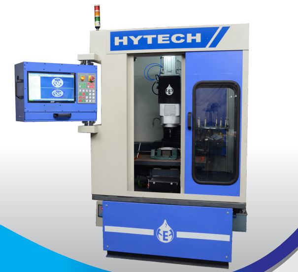
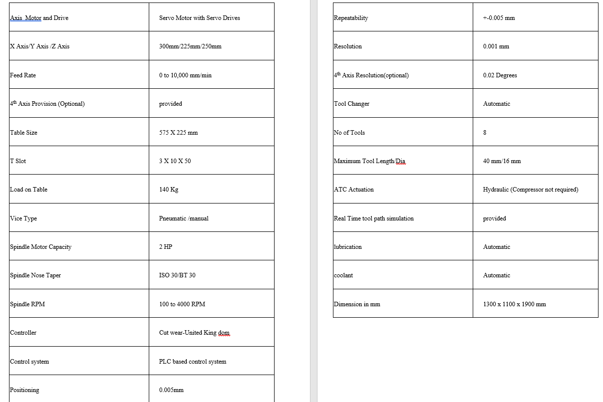
| 13 | CNC Mill Trainer |
  |
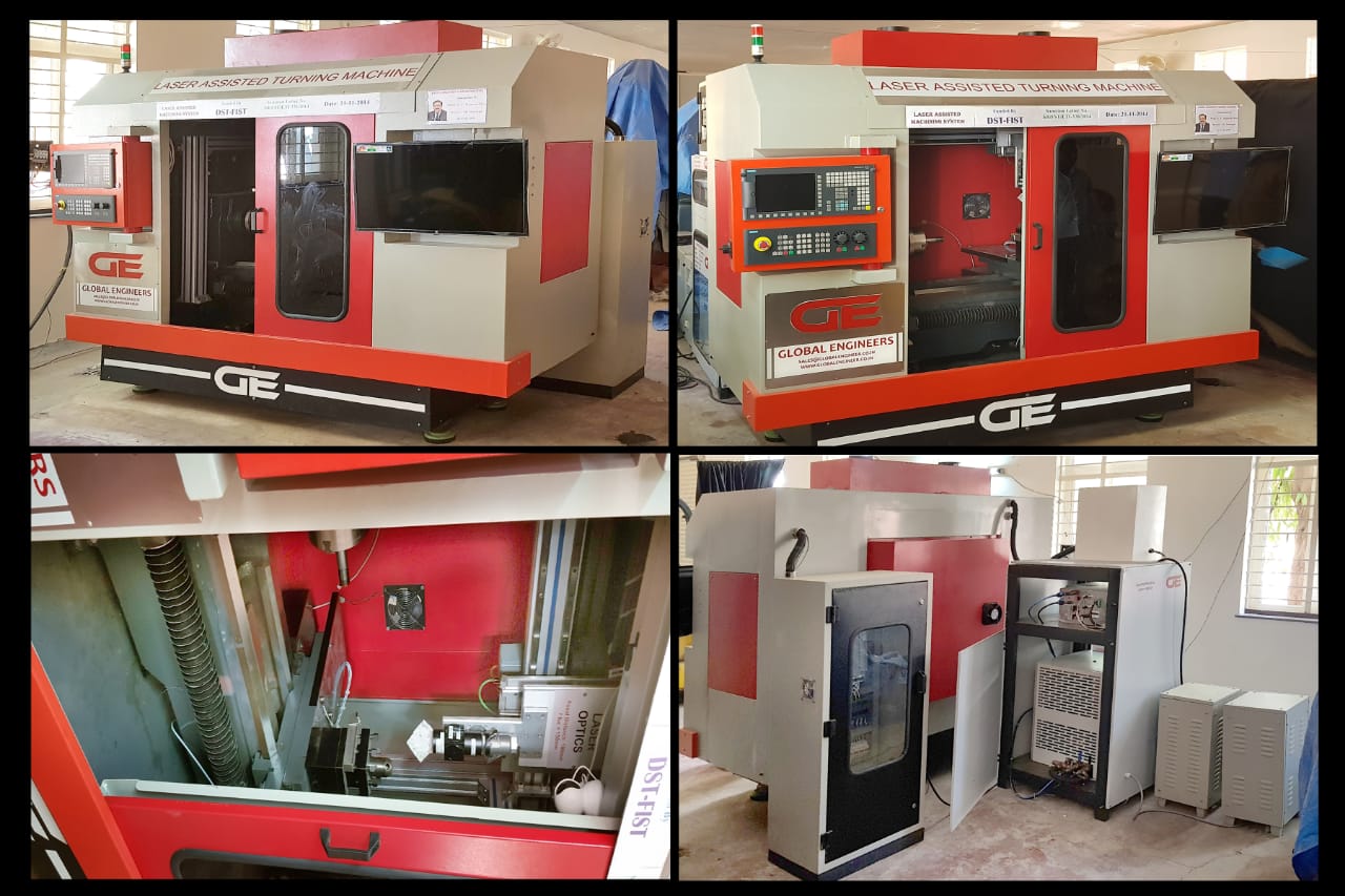
| 14 | Laser Assisted Machining System |
 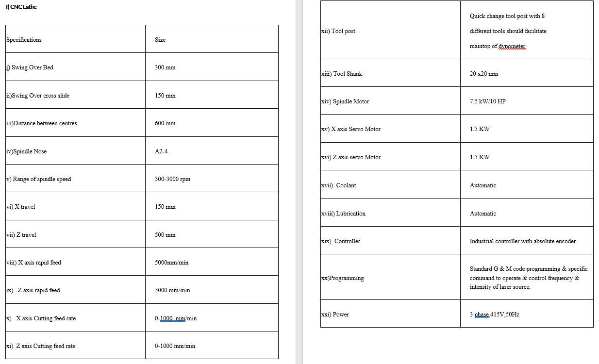 |
| 15 | High Temperature Muffle Furnace | 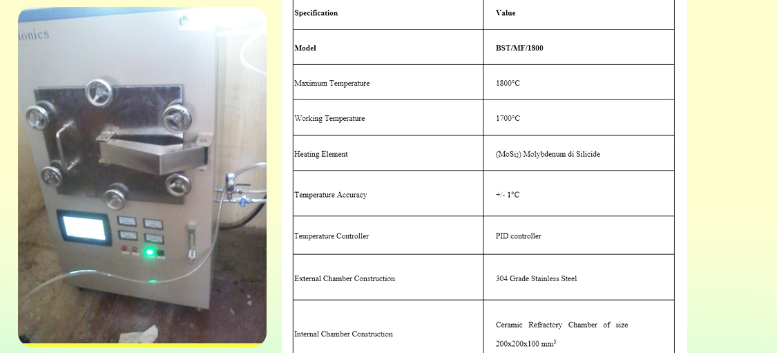 |
Thermal Engineering Labs
|
Utility: Heat Transfer Laboratory caters to the needs of B.Tech. 3rd year Mechanical Engineering and M.Tech. Thermal Engineering. There are 8 experimental setups available in the laboratory:
These experiments help students understand all the 3 modes of heat transfer, namely conduction, convection and radiation practically. These experiments also pave way for inculcating certain innovative skills in the students, making them use the above experimental setups as a starting point to take up higher level experimental studies in Heat Transfer. |
|
The I.C. Engine Lab hosts the following major experimental setups: |
| # | Equipment | Description & Experimental Capabilities |
|---|---|---|
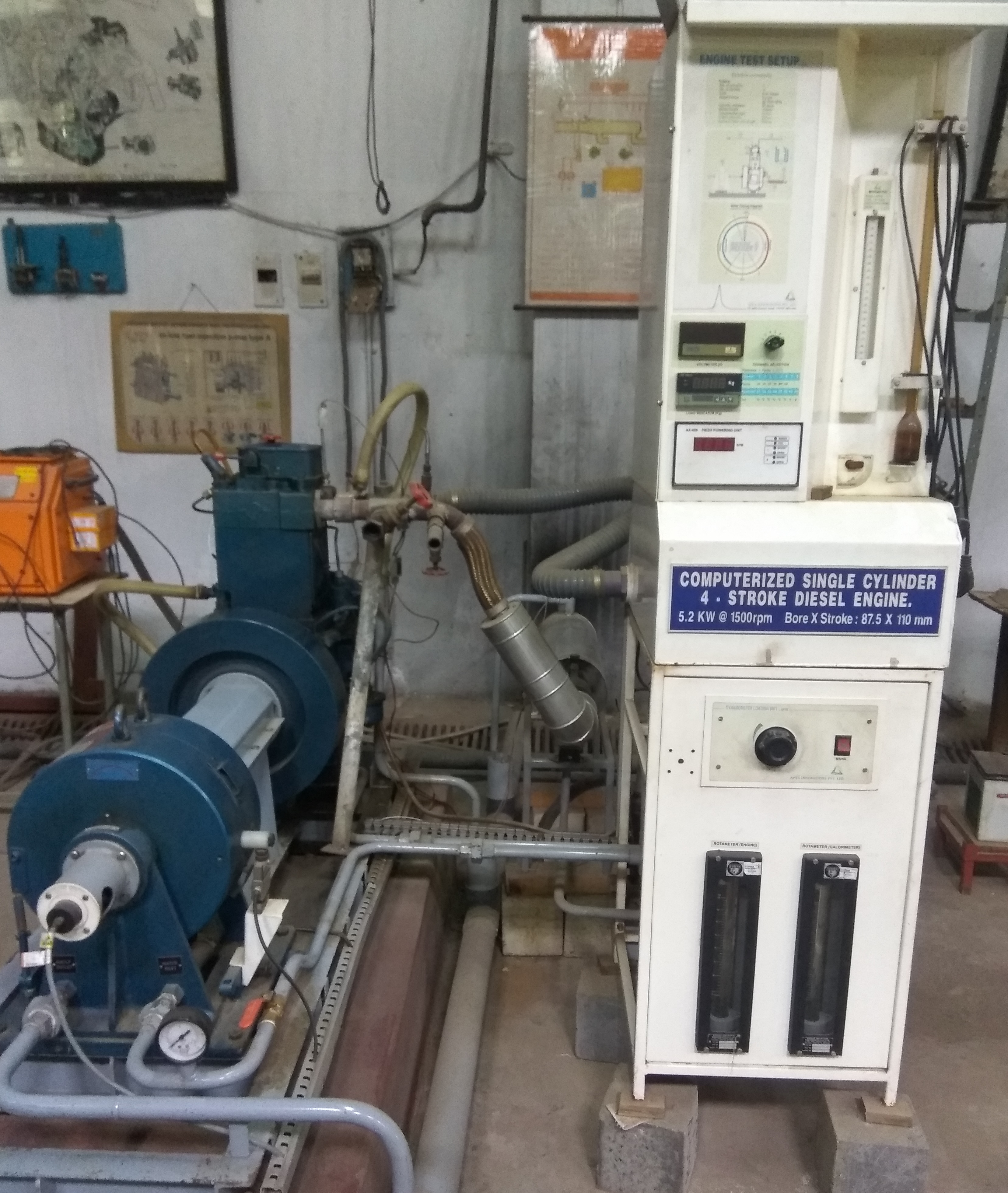
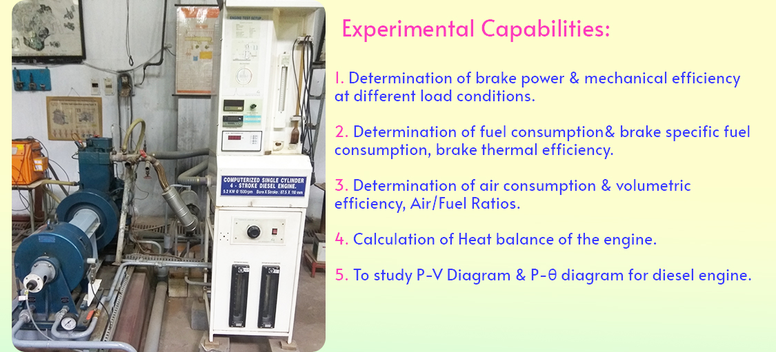
| 1 | Computerized Single Cylinder 4-Stroke Diesel Engine |
This setup consists of a four stroke Diesel Engine coupled to a suitable eddy current type dynamometer. The engine is single cylinder, water cooled, running at constant speed. The dynamometer provides the variable load on the engine to study engine performance under variable load conditions. Exhaust gas calorimeter is used for estimation of heat carried away by exhaust gases for determination of heat balance. Air is supplied through an air box fitted with orifice plate. The instrumentation console includes measuring instruments for Engine Speed, Torque, Air consumption, Fuel Consumption, temperature & cooling water flow rates. Parameters are recorded by sensors & transmitted to Data Acquisition Device which sends the data to computer. Windows-based software developed in LabView Platform is capable of displaying real-time acquired data in graphical & numerical format.
  |
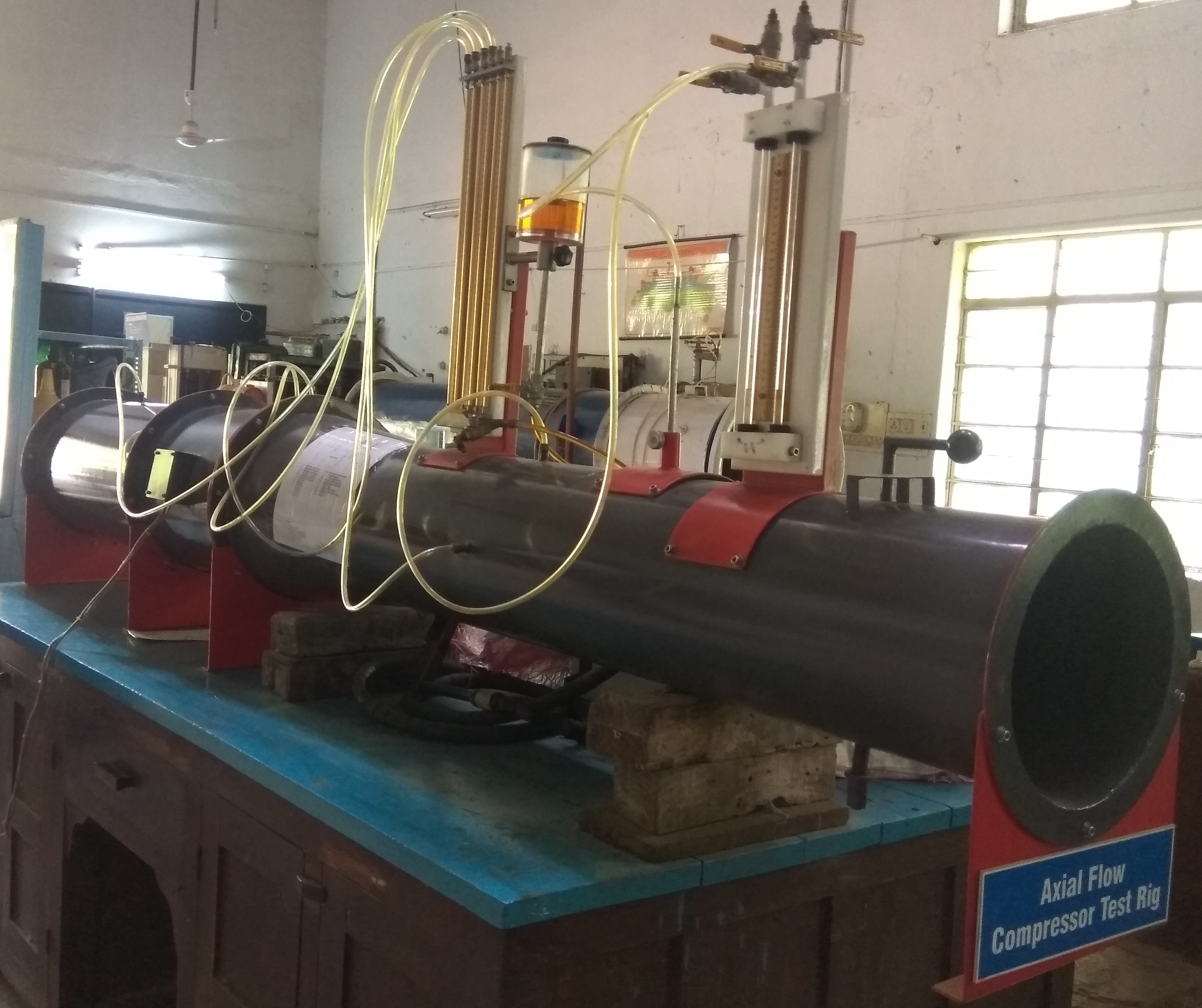
| 2 | Axial Flow Compressor Test Rig |
An axial compressor is a gas compressor that can continuously pressurize gases. It is a rotating, airfoil based compressor in which the gas or working fluid principally flows parallel to the axis of rotation. The energy level of the fluid increases as it flows through the compressor due to the action of the rotor blades which exert a torque on the fluid. The stationary blades slow the fluid, converting the circumferential component of flow into pressure. Axial flow compressors produce a continuous flow of compressed gas, with the benefits of high efficiency and large mass flow rate, particularly in relation to their size and cross-section.
Tests performed with the setup:
|
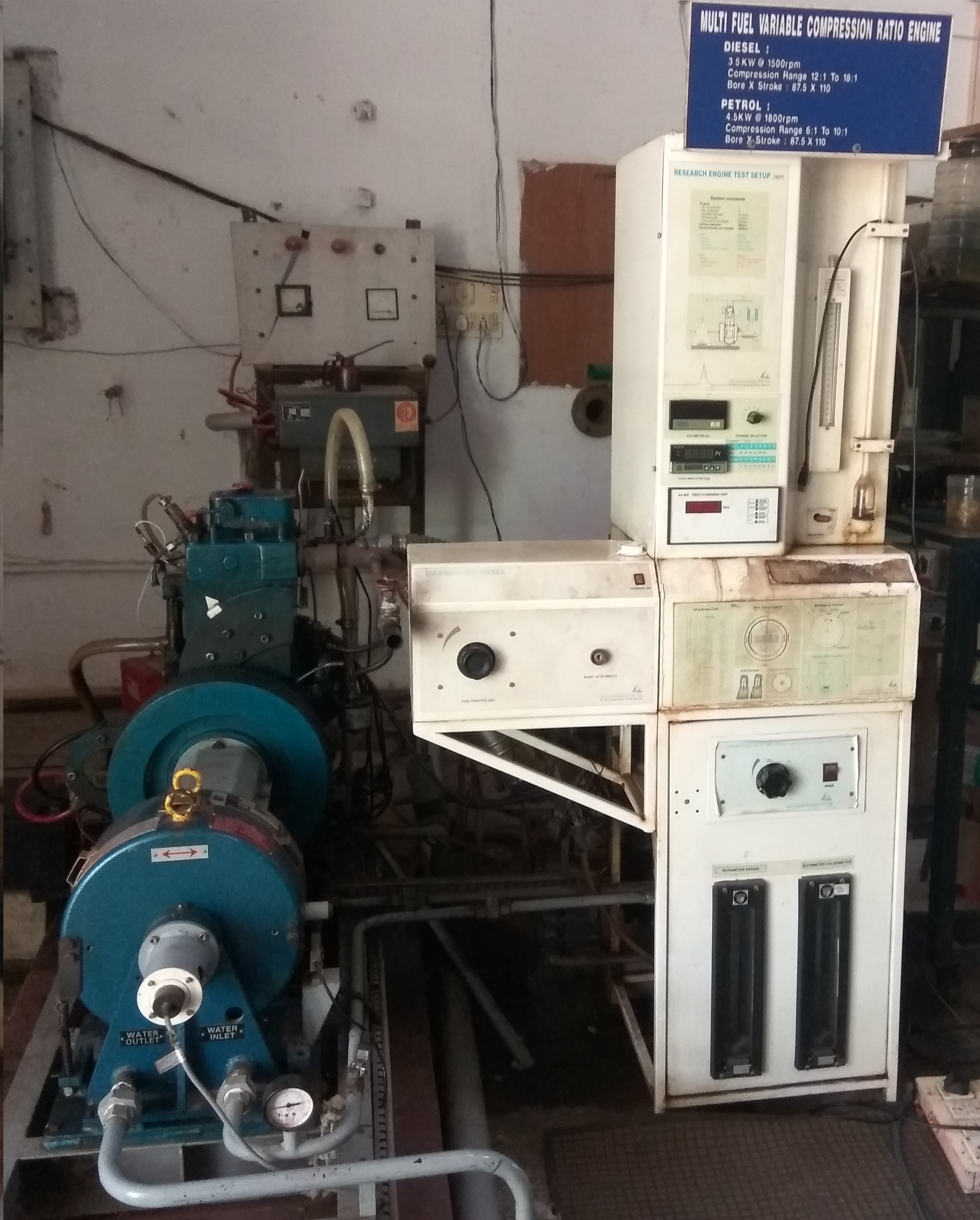
| 3 | Multi Fuel Variable Compression Ratio Engine |
The Multifuel VCR Engine Setup consists of a single cylinder, four stroke, VCR (Variable Compression Ratio) Diesel engine connected to eddy current type dynamometer for loading. Compression ratio can be changed without stopping the engine and without altering the combustion chamber geometry by a specially designed tilting cylinder block arrangement. Setup is provided with necessary instruments for combustion pressure and crank-angle measurements. Signals are interfaced to computer through engine indicator for Pθ-PV diagrams. Provision is also made for interfacing airflow, fuel flow, temperatures and load measurement. Stand-alone panel box consists of air box, two fuel tanks for blend test, manometer, fuel measuring unit, transmitters for air and fuel flow measurements, process indicator and engine indicator. Rotameters are provided for cooling water and calorimeter water flow measurement. LabVIEW based Engine Performance Analysis software package "ICEngineSoft" is provided for online performance evaluation.
Experimental Capabilities:
|
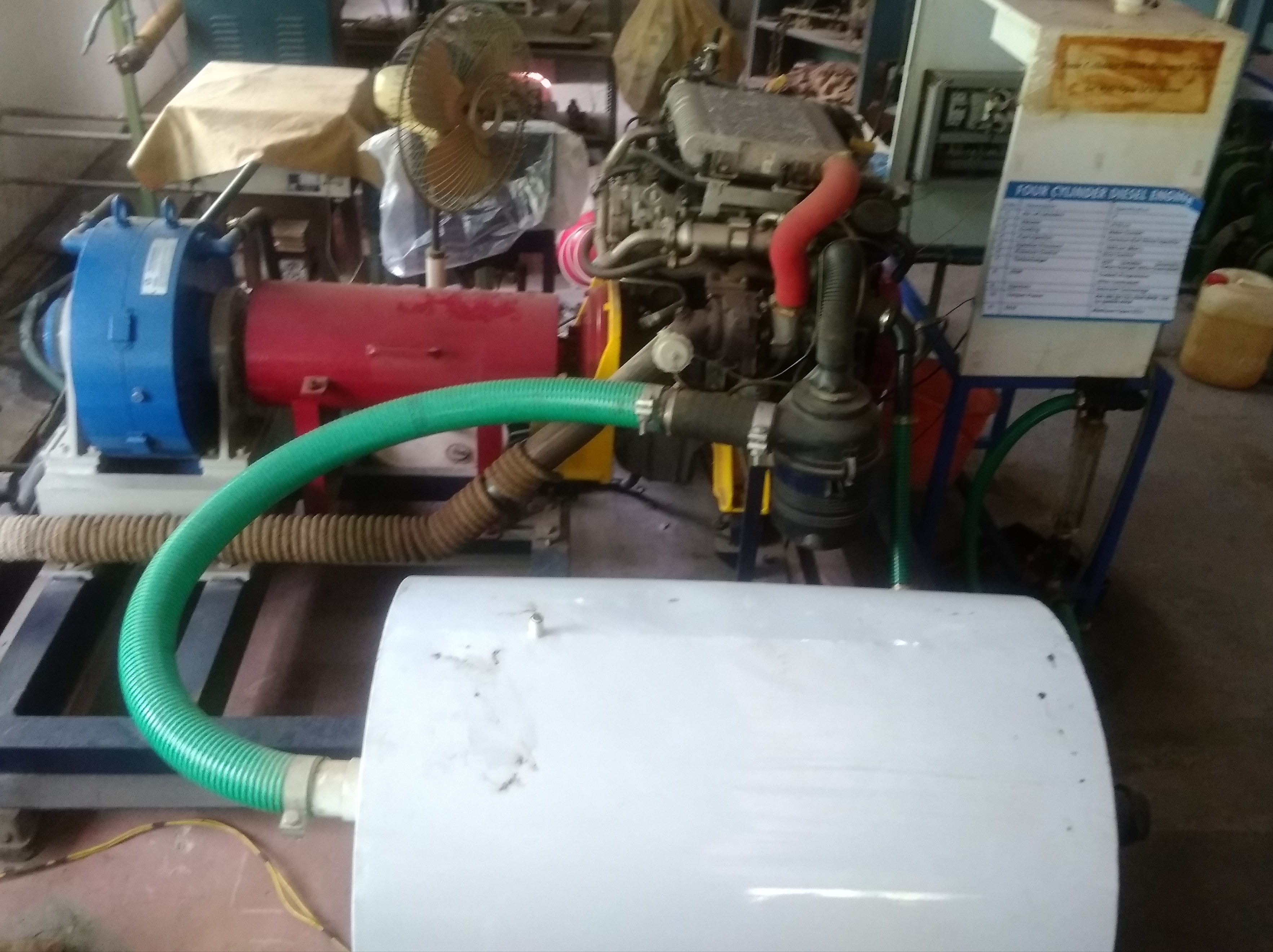
| 4 | Four-Cylinder Automotive CRDi Variable Geometry Turbocharger Engine |
The engine is a four cylinder water cooled four stroke automotive diesel engine. Diesel fuel is injected directly into the combustion chamber with common-rail fuel injection equipment. Fuel parameters like fuel quantity, injection timing, number of injections, fuel pressure in the rail, etc. can be changed online with the help of an Open ECU. Open ECU based variation in above parameters simplifies the research by bringing so many parameters in the preview of research. These parameters can be optimized by click of mouse at various rpm points to study their effect on Engine efficiency, Ignition delay, Emission etc.
Experimental Capabilities:
|
| 5 | Four-Wheeler Chassis Dynamometer with Brake Retarders |
It is a mechanical device for measuring power and torque of a car, bike, truck or even an agricultural machine. Sometimes it is called a Rolling road. The torque produced by an engine is converted to traction force by transmission (gearbox, differential) at wheels. Chassis dynamometers can be used not only for simple torque and power measurement. Very common usage is fuel consumption and emissions measurement or to determine real fuel consumption under load.
A chassis dynamometer is a device that can simulate the resistance imposed on the wheel of a vehicle according to different driving cycles. During testing, the vehicle is tied and running on loading controllable rollers keeping a stationary state. According to the predefined time-velocity curve shown on a monitor, the driver operates the vehicle to match the curve in different driving cycles. The exhaust gas is then output to an online exhaust gas analyser for emission measurement. DAC, or data acquisition system is an integral part of a chassis dynamometer. It commands the load (if the brake is installed), measures rotational speeds, acceleration of rollers, resistance force generated at the electromagnetic brake. Advanced dynos offer also a possibility of measuring other parameters that are important for a car tuner or a workshop — AFR (air to fuel ratio of mixture), EGT (exhaust gas temperature), MAP (manifold absolute pressure boost). 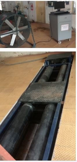
|
|
Objective: To facilitate B.Tech students in understanding the working principle of mechanical measuring devices and sensors and to train them to operate and calibrate them. Lab CoverageDisplacement Measurement, Humidity Measurement, Level Measurement, Flow Measurement, Load Measurement, Velocity Measurement, Temperature Measurement and Torque Measurement. |
| # | Equipment | Description & Experimental Capabilities |
|---|---|---|
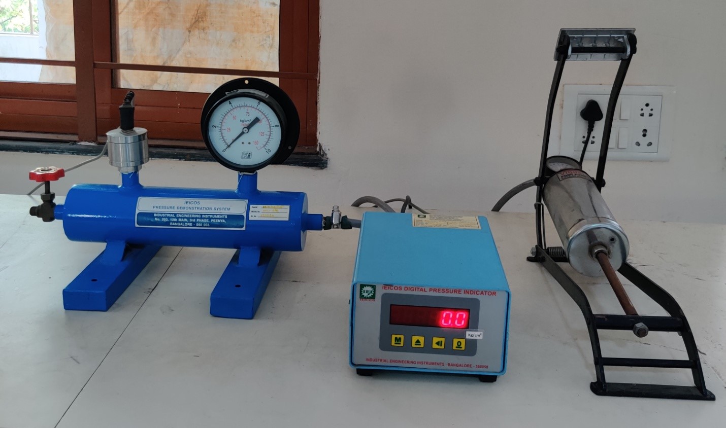
| 1 | Pressure Measurement using Strain Gauge Pressure Transducer |
Strain gauge pressure transducer is an electro-mechanical device manufactured and designed for wide range of applications in pressure measurement. A common method for converting diaphragm displacement into a measurable signal is to sense the strain induced on the diaphragm surface as it is displaced. Strain gauges, devices whose measurable resistance is proportional to their sensed strain, can be bonded directly onto the diaphragm, integrated within the diaphragm material or onto a deforming element (such as a thin beam) attached to the diaphragm so as to deform with the diaphragm and to sense strain. Metal strain gauges can be used with liquids. Strain gauge resistance is reasonably linear over a wide range of strain and can be directly related to the sensed pressure.
By using semiconductor technology in pressure transducer construction, we now have a variety of very fast, very small, highly sensitive strain gauge diaphragm transducers. Silicone piezo resistive strain gauges can be diffused into a single crystal of silicon wafer which forms the diaphragm. Semiconductor strain gauges have a static sensitivity that is 50 times greater than conventional metallic strain gauges. Experimental Capabilities:
|
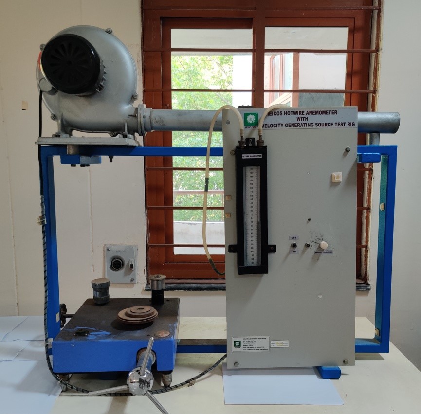
| 2 | Flow Velocity Measurement using Pitot Tube and Hot Wire Anemometer |
Flow measurement gives the idea in understanding the flow nature in liquids and gases. Instruments like the pitot tube and hot wire anemometers measure the local velocity at a point in the channel or duct through which fluid is flowing.
Pitot tube: An instrument used to measure fluid flow velocity based upon Bernoulli's principle. Flow velocity constitutes important parameters like kinematics and dynamics of fluid flow. This fluid velocity meter measures the local velocity at a point in the flow duct, and is used mainly for the measurement of air or gas velocities. Its value of Cv lies between 0.95 and 1.0. Hot wire anemometer: An instrument used to measure the mean and fluctuating flow components in a flow field. The sensor is a 5 microns diameter platinum-tungsten wire welded between the two prongs of the probe and heated electrically as a part of a Wheatstone bridge circuit. When the probe is introduced into the flow field, it tends to be cooled by the instantaneous velocity and consequently there is a tendency for the electrical resistance to diminish. Experimental Capabilities:
|
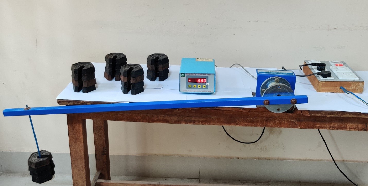
| 3 | Torque Measurement using Strain Gauges |
The measurement of torque is important in a variety of applications, including sizing of load-carrying shafts. This measurement is also a crucial aspect of the measurement of shaft power, such as in an engine dynamometer. Strain-gauge–based torque cells are constructed in a manner similar to load cells, in which a torsional strain in an elastic element is sensed by strain gauges appropriately placed on the elastic element. A circular shaft is instrumented with strain gauges for the purpose of measuring torque.
Experimental Capabilities:
|
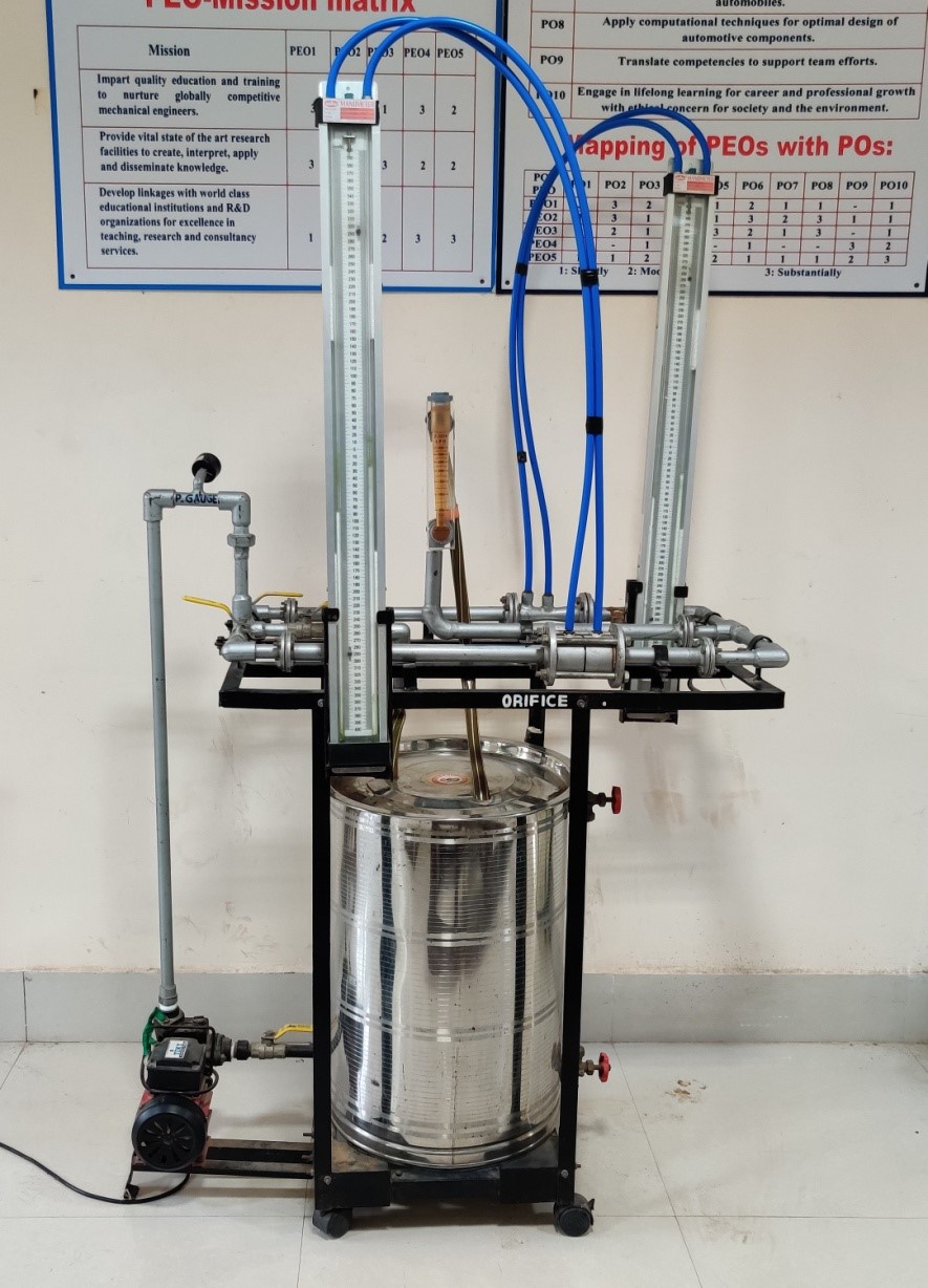
| 4 | Flow Measurement by Venturi and Orifice Meter |
Venturi meter and orifice meter are commonly used flow meters for measuring mass/volumetric flow rate or velocity of the flowing fluid. These flow meters are also known as variable head meters, categorized as full-bore meters as the measurement of the fluid takes place when it flows through a conduit or channel.
Venturi meter: The venturi meter has a converging conical inlet, a cylindrical throat and a diverging recovery cone. It has no projections into the fluid, no sharp corners and no sudden changes in contour. Orifice meter: The orifice meter consists of an accurately machined and drilled plate concentrically mounted between two flanges. The orifice meter has several practical advantages when compared to venturi meters — lower cost, smaller physical size and flexibility to change throat-to-pipe diameter ratio to measure a larger range of flow rates. Experimental Capabilities:
|